Liquid cooling heat dissipation module, liquid cooling heat dissipation system and electronic equipment

A technology for liquid cooling and heat dissipation of electronic equipment, which is applied to structural components of electrical equipment, cooling/ventilation/heating transformation, circuits, etc., and can solve the problem of low integration, single micro-pump easy to get stuck in the working medium circulation, and the volume of the cooling system Major and other issues

Pending Publication Date: 2020-10-23
常州威图流体科技有限公司
View PDF0 Cites 13 Cited by
  • Summary
  • Abstract
  • Description
  • Claims
  • Application Information

AI Technical Summary

Problems solved by technology

[0004] The purpose of the present invention is to provide a liquid-cooled heat dissipation module to solve the problem of large volume and low integration in the heat dissipatio...

Method used


Image

  • Liquid cooling heat dissipation module, liquid cooling heat dissipation system and electronic equipment
  • Liquid cooling heat dissipation module, liquid cooling heat dissipation system and electronic equipment
  • Liquid cooling heat dissipation module, liquid cooling heat dissipation system and electronic equipment

Examples


Embodiment 1

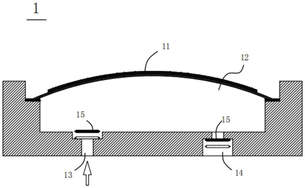
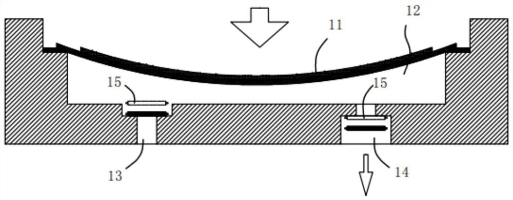
[0061] see Figure 1-4 , the liquid-cooled heat dissipation module provided in this embodiment includes a power pump 1 and a pressure regulating module 2. The power pump 1 provides power for the heat dissipation circuit, and the pressure regulation module 2 and the power pump 1 are connected in series on the heat dissipation circuit. When working, at the same time , the sum of the volume change of the pump chamber 12 caused by the power pump 1 and the volume change of the pressure regulating chamber of the pressure regulating module 2 approaches zero. Specifically, when the power pump 1 is in the suction range, the pressure regulating module 2 is in the discharge range , the fluid flows in one direction in the channel 3, and the volume increase of the pump chamber 12 of the power pump 1 is basically equal to the decrease of the volume of the pressure regulating module 2, so that the volume change of the pump chamber 12 caused by the power pump 1 The sum of the volume changes o...

Embodiment 2

[0071] Such as Figure 10 As shown, the structure of this embodiment is basically the same as that of Embodiment 1, the difference is that the pressure regulating module 2 is an active pressure regulating structure, and the active pressure regulating structure includes a cavity 21a and an active plate 22a, and the cavity 21a Configured as the pressure regulating chamber, the chamber 21a communicates with the flow channel 3, and the part of the active plate 22a opposite to the chamber 21a can bend and vibrate, thereby driving the fluid in the chamber 21a to enter and exit. Its working principle is the same as that of Embodiment 1, and will not be repeated here.

Embodiment 3

[0073] Such as Figure 11 As shown, the structure of this embodiment is basically the same as that of Embodiment 1, the difference is that the pressure regulation module 2 is a passive pressure regulation structure, and the passive pressure regulation structure includes an elastic diaphragm 22b and an elastic chamber 21b, and the elastic diaphragm 22b is at least In the working state, it is formed into a curved structure, and the concave surface of the curved structure forms an elastic cavity 21b;

[0074] The elastic cavity 21b is configured as the pressure regulating cavity, and the elastic cavity 21b communicates with the flow channel 3 . In this way, the elastic cavity 21b can be adaptively changed along with the suction stroke and discharge stroke of the power pump 1 , thereby playing the role of balancing flow channel pressure.


PUM


Abstract

The invention relates to the technical field of heat dissipation systems. A liquid cooling heat dissipation module comprises a heat dissipation module comprises a power pump and a pressure regulatingmodule, the power pump provides power for the heat dissipation loop; the pressure regulating module and the power pump are connected in a heat dissipation loop in series. During work, at the same moment, the sum of the pump cavity volume variation caused by the power pump and the pressure regulating cavity volume variation of the pressure regulating module approaches zero, so that the pressure inthe pipeline is in a balanced state, the problem of sudden stop of working medium circulation caused by clamping stagnation of a single power pump is solved, and meanwhile flow channel tremor is avoided. Meanwhile, due to the fact that a liquid storage tank is omitted, the problems that a traditional liquid cooling heat dissipation module is large in size and not high in integration degree are effectively solved, the size of a heat dissipation system is smaller, and miniaturization of products is facilitated.

Description

technical field [0001] The invention relates to the technical field of heat dissipation systems, and specifically relates to a liquid-cooled heat dissipation module, a liquid-cooled heat dissipation system and electronic equipment. Background technique [0002] With the vigorous development of microelectronics, micromechanics, micro-optics and other fields, as well as the development and application of large-scale and ultra-large-scale integrated circuits, the power consumption of products continues to increase, and the problems of heat conduction and heat dissipation in small spaces have become increasingly prominent. [0003] The current heat dissipation technologies mainly include metal heat dissipation, air cooling, liquid cooling and gas-liquid phase change heat dissipation, among which liquid cooling can provide higher cooling power because its circulating working medium is much larger than the heat capacity per unit volume of gas. Become the best choice, and will also...

Claims


Application Information

Patent Timeline
IPC IPC(8): H05K7/20H01L23/473
CPCH01L23/473H05K7/20218H05K7/20272H05K7/20281
Inventor 不公告发明人
Owner 常州威图流体科技有限公司
Why Eureka
Try Eureka