Tin soldering device for electronic product production

A technology for electronic products and soldering, applied in auxiliary devices, welding equipment, metal processing, etc., can solve the problems of waste of electric energy and untargeted gas absorption.

Inactive Publication Date: 2020-10-27
SUZHOU YUQIAN INFORMATION TECH CO LTD
View PDF0 Cites 0 Cited by
  • Summary
  • Abstract
  • Description
  • Claims
  • Application Information

AI Technical Summary

Problems solved by technology

[0003] A soldering device for the production of electronic products is needed when soldering the components of electronic products. However, when the current soldering devices for electronic products are in use, the solder will volatilize into Toxic gas, most of the soldering equipment does not deal with

Method used


Image

  • Tin soldering device for electronic product production
  • Tin soldering device for electronic product production
  • Tin soldering device for electronic product production

Examples


Embodiment 1

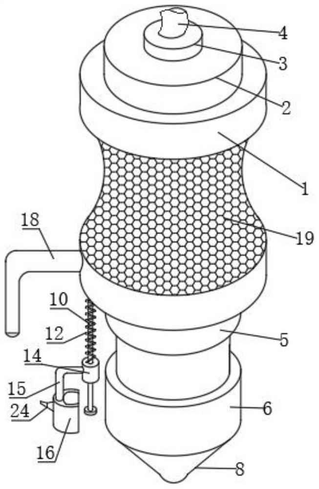
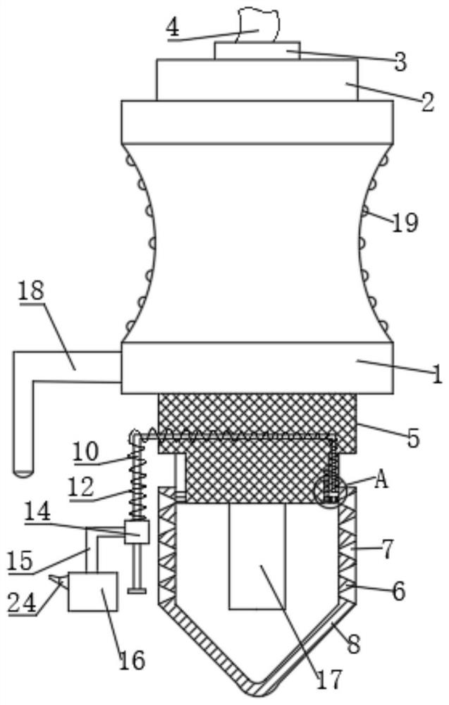
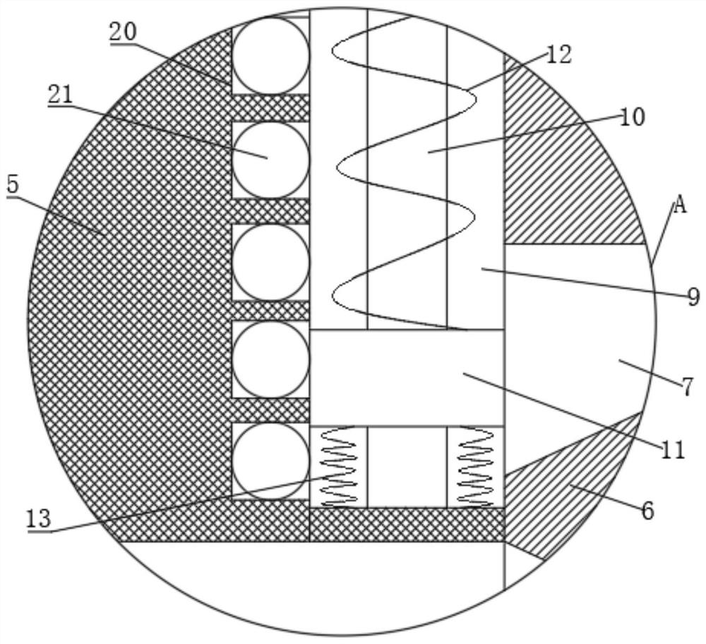
[0026] refer to Figure 1-3 , a soldering device for the production of electronic products, comprising a hand-held tube 1, a support column 2 is welded on the top of the hand-held tube 1, a wire harness ring 3 is welded on the top of the support column 2, and a wire 4 is threaded inside the wire harness ring 3, The bottom of the hand tube 1 is welded with a connecting rod 5, the bottom of the connecting rod 5 is nested and slidably connected to a heat pipe 6, the bottom of the heat pipe 6 is welded with a soldering tip 8, the connecting rod 5 is pierced with a guide rod 10, and the cross section of the guide rod 10 is Set to U-shape, two chutes 9 are provided symmetrically on both sides of the connecting rod 5, the bottom of the guide rod 10 and the bottom of the inner wall of the chute 9 are fixed by bolts, and the guide rod 10 is connected with a sliding block 11 through sliding, the outer side of the sliding block 11 and the inner wall bottom of the chute 9 are fixed by bolt...

Embodiment 2

[0030] refer to Figure 1-5 , a soldering device for the production of electronic products, the cross section of the exhaust box 16 is arranged in an arc shape, the inner surface of the exhaust box 16 is provided with a plurality of protrusions 22, the cross section of the protrusions 22 is arranged in an arc shape, and the protrusions 22 are provided with Fine air extraction holes 23, the exhaust mechanism is fixed with a support rod 25 by bolts inside the exhaust box 16, a motor 26 is fixed on the inside of the support rod 25 by bolts, the output shaft of the motor 26 is connected with an exhaust fan 27, and the exhaust box 16 is away from One side of the air extraction hole 23 is fixed with an exhaust pipe 24 by bolts, and the exhaust pipe 24 is arranged to be bent and narrowed from the inside out.

[0031] During use, start the motor 26, and the motor 26 drives the exhaust fan 27 to rotate and exhaust. The exhaust box 16 cross-sections are arranged in an arc shape, so that...


PUM


Abstract

The invention belongs to the technical field of electronic products, and particularly relates to a tin soldering device for electronic product production. A scheme is presented with regard to the problem of a tin soldering device wasting electrical energy. According to the scheme, the tin soldering device comprises a handheld pipe; the bottom of a connecting rod is in embedding sliding connectionwith a heat conducting pipe; a tin soldering tip is welded to the bottom of the heat conducting pipe; a guiding rod is mounted in the connecting rod in a penetrating mode; a sliding block is slidablyconnected to the guiding rod; a first spring is welded to the top of the sliding block; a fixing ring sleeves the guiding rod; the other side of the first spring is fixed to the top of the fixing ring; a supporting rod is fixed to the outer side of the fixing ring; an exhausting box is fixed to the bottom of the supporting rod; and an exhausting mechanism is mounted in the exhausting box. According to the tin soldering device for electronic product production, during spot welding, the tin soldering tip drives the heat conducting pipe and the sliding block to move upwards, and the first springis stressed to sequentially drive the fixing ring, the supporting rod and the exhausting box to move downwards, so that the exhausting mechanism is close to an electric welding position to exhaust poisonous gases, the tin soldering device is used for exhausting pertinently, and electric energy is saved on the premise of ensuring the exhausting effect.

Description

technical field [0001] The invention relates to the technical field of electronic products, in particular to a soldering device for electronic product production. Background technique [0002] Electronic products are related products based on electric energy, mainly including: watches, smart phones, telephones, televisions, video disc players (VCD, SVCD, DVD), video recorders, camcorders, radios, tape recorders, combination speakers, CD players (CD), computers, mobile communication products, etc. Because the early products were mainly based on electronic tubes, they were named electronic products. During the production and processing of electronic products, most of them require soldering of electronic product production parts. [0003] A soldering device for the production of electronic products is needed when soldering the components of electronic products. However, when the current soldering devices for electronic products are in use, the solder will volatilize into Tox...

Claims


Application Information

Patent Timeline
IPC IPC(8): B23K3/00B23K3/08
CPCB23K3/00B23K3/08
Inventor 沈丽红
Owner SUZHOU YUQIAN INFORMATION TECH CO LTD
Why Eureka
Try Eureka