
Manufacturing method for automobile central control box and new energy automobile

A manufacturing method and the technology of the central control box, applied in the direction of manufacturing tools, non-electric welding equipment, welding equipment, etc., can solve the problems of troublesome line connection, high production cost, large consumables, etc.

Inactive Publication Date: 2020-10-27
广东九九华立新材料股份有限公司
View PDF11 Cites 0 Cited by
  • Summary
  • Abstract
  • Description
  • Claims
  • Application Information

AI Technical Summary

Problems solved by technology

[0002] As new energy vehicles become more and more popular, the central control box of the car is an important part of the control system of the new energy vehicle. The control system involves many components. In order to meet the placement and integration of various systems, the existing control system is placed in different In the box, each box is matched and connected. This method increases the weight of the entire car body, and the connection between the various parts is troublesome, the production process is cumbersome, and the production cost is high. There are certain limitations in the application of new energy vehicles. sex
In order to reduce the assembly parts of the car as much as possible, reduce the weight of the car body, and reduce energy consumption, a central control box that integrates various control modules into one box appeared later. However, due to the large number of integrated modules, the heat dissipation performance is not good, and high-pressure casting is used. The mold opening cost is high and the mold opening cycle is long. In the case of friction stir welding, only the welding surface has crystals, which is prone to virtual welding, large consumables, poor air tightness and mechanical properties of the product, and easy Bubbles are generated, and desoldering is prone to occur in a vibrating environment or under impact, which is difficult to meet the current requirements of light weight and high heat dissipation performance of new energy vehicles

Method used


Image

  • Manufacturing method for automobile central control box and new energy automobile

Examples


Embodiment Construction

[0021] The following will clearly and completely describe the technical solutions in the embodiments of the present invention with reference to the accompanying drawings in the embodiments of the present invention. Obviously, the described embodiments are some of the embodiments of the present invention, but not all of them. Based on the embodiments of the present invention, all other embodiments obtained by persons of ordinary skill in the art without making creative efforts belong to the protection scope of the present invention.

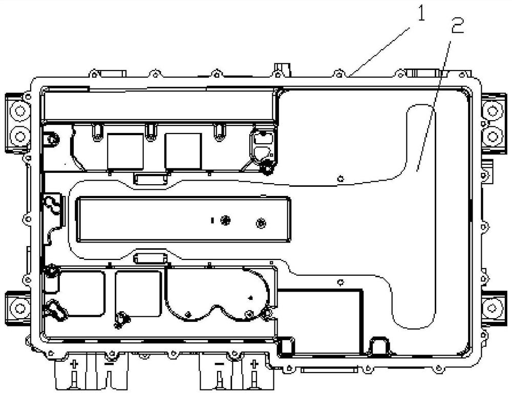
[0022] The invention provides a method for manufacturing a central control box of an automobile, comprising the following steps: selecting an aluminum ingot for making the main body of the central control box and an aluminum plate for making a waterway cover plate; performing low-pressure casting on the aluminum ingot to produce The main body of the central control box with a water channel; the aluminum plate is washed by CNC to form a water channe...


PUM


Abstract

The invention discloses a manufacturing method for an automobile central control box. A low-pressure casting mode is adopted to manufacture a central control box body with a water channel; a water channel cover plate with a water flow groove is flushed in a CNC mode; and then the water channel cover plate is welded to the water channel of the central control box body through friction welding, andthe welded water channel cover plate and the central control box body form a sealed cavity. The central control box body with the water channel is manufactured in the low-pressure casting mode, the water channel cover plate with the water channel is manufactured in the CNC mode, and the central control box body and the water channel cover plate are welded in the friction welding mode, a brand-newprocess is formed. When the process is used for manufacturing the central control box, the mold opening cost is low, the mold opening period is short, the process is simplified, the produced automobile central control box is good in air impermeability and mechanical performance, the production cost is saved, and the formed central control box is high in integration level.

Description

technical field [0001] The invention relates to the technical field of auto parts manufacturing, in particular to a method for manufacturing a central control box used in new energy vehicles. Background technique [0002] As new energy vehicles become more and more popular, the central control box of the car is an important part of the control system of the new energy vehicle. The control system involves many components. In order to meet the placement and integration of various systems, the existing control system is placed in different In the box, each box is matched and connected. This method increases the weight of the entire car body, and the connection between the various parts is troublesome, the production process is cumbersome, and the production cost is high. There are certain limitations in the application of new energy vehicles. sex. In order to reduce the assembly parts of the car as much as possible, reduce the weight of the car body, and reduce energy consumpt...

Claims


Application Information

Patent Timeline
IPC IPC(8): B23P15/00B22D18/04B23K20/12
CPCB23P15/00B22D18/04B23K20/12
Inventor 慈晟
Owner 广东九九华立新材料股份有限公司
Learn More