Floating disc mechanism

A technology of floating disk and chuck, which is applied in the direction of conveying filamentous materials, thin material processing, transportation and packaging, etc. It can solve the problems of poor quality, failed winding and loose quality, so as to achieve high work efficiency, save overall space, Safe and reliable results at work

Pending Publication Date: 2020-10-27
张家港市瑞昌智能机器系统有限公司
View PDF0 Cites 0 Cited by
  • Summary
  • Abstract
  • Description
  • Claims
  • Application Information

AI Technical Summary

Problems solved by technology

[0004] In order to solve the problems of failure in winding switching between full and empty I-shaped wheels and loose winding quality during the winding process, this invention proposes a floating disc mechanism to solve this problem

Method used


Image

  • Floating disc mechanism
  • Floating disc mechanism
  • Floating disc mechanism

Examples


Embodiment Construction

[0018] The following will clearly and completely describe the technical solutions in the embodiments of the present invention with reference to the accompanying drawings in the embodiments of the present invention. Obviously, the described embodiments are only some, not all, embodiments of the present invention. Based on the embodiments of the present invention, all other embodiments obtained by persons of ordinary skill in the art without creative efforts fall within the protection scope of the present invention.

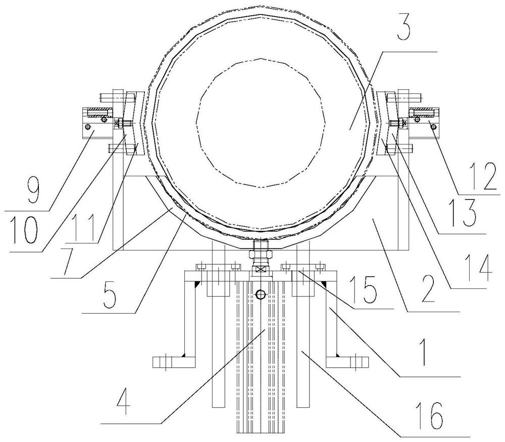
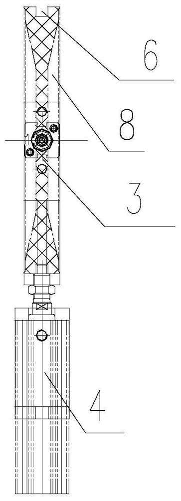
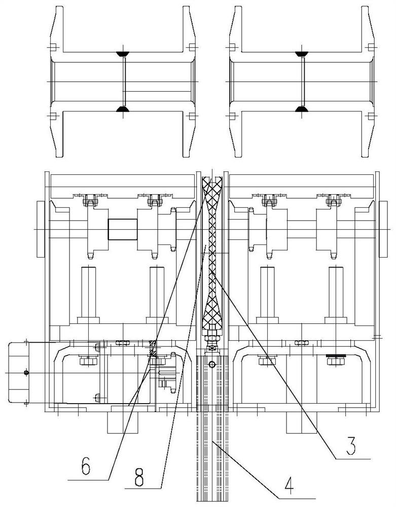
[0019] Such as Figure 1-2 As shown, the floating disk mechanism of the present invention includes a fixed frame 1, a first actuator 4 installed on the fixed frame 1, a tray 2 and a transition disk 3 arranged in the tray 2, and the protruding end of the first actuator 4 is connected to At the bottom of the tray 3, the tray 3 has a semicircular arc-shaped groove 5 that matches the outer cylindrical surface of the transition disc 3. The tray 2 is also provided with a...


PUM


Abstract

The invention relates to a floating disc mechanism. The floating disc mechanism comprises a fixing frame, a first executing piece, a tray and a transition disc, wherein the first executing piece, thetray and the transition disc are arranged on the fixing frame, the extending end of the first executing piece is connected with the bottom of the tray, the tray is internally provided with a semicircular arc-shaped groove matched with the outer cylindrical surface of the transition disc, the tray is further provided with a disc clamping group used for clamping the transition disc, the outer cylindrical surface of the transition disc is circumferentially provided with a groove, a first arc-shaped boss matched with the groove is arranged at the position, corresponding to the groove, of the arc-shaped groove, end face structures matched with the end faces of spools in shape are arranged on the two end faces of the transition disc, and the diameters of the two end faces of the transition discare equivalent to the diameters of the end faces of the spools. The floating disc mechanism is arranged between two spool conveying frames, so that the whole space is saved, the structure is compact,and the operation is safe and reliable; when a full wheel and an empty wheel are switched in wire winding, seamless transition is realized, winding is not scattered, winding quality is better, and working efficiency is higher.

Description

technical field [0001] The invention relates to an auxiliary mechanism for an I-shaped shift line without stopping the main engine, in particular to a floating disk mechanism. Background technique [0002] The take-up machine equipment is mainly used for take-up in the production process of optical fiber and cable; take-up in the production process of serial lines, twisted pairs, cabling, etc. of data communication cables; it is also suitable for high-knit machine take-up of radio frequency cables, wires and cables , High stranding machine take-up, extruder take-up, winding machine take-up, etc., are widely used. [0003] In the actual winding process, when switching the winding of the full I-shaped wheel and the empty I-shaped wheel, the end faces of the full I-shaped wheel and the empty I-shaped wheel set in parallel need to be infinitely close, and the end faces of the I-shaped wheel generally have a taper , even if the end faces of the full I-shaped wheel and the empty ...

Claims


Application Information

Patent Timeline
Patent Type & Authority Applications(China)
IPC IPC(8): B65H54/20B65H67/044
CPCB65H54/205B65H67/044B65H2701/32B65H2701/34
Inventor 王波王富礼史修进
Owner 张家港市瑞昌智能机器系统有限公司
Why Eureka
Try Eureka