Magnetron tube for carrying out magnetron sputtering

A magnetron and magnetic bar technology, which is applied in sputtering coating, ion implantation coating, metal material coating process, etc., can solve the problems of affecting the sputtering effect, internal cracking, uneven magnetic field on the target surface, etc.

Pending Publication Date: 2020-10-27
ZHEJIANG SHANGFANG ELECTRONICS EQUIP
View PDF6 Cites 2 Cited by
  • Summary
  • Abstract
  • Description
  • Claims
  • Application Information

AI Technical Summary

Problems solved by technology

Since the magnetic field intensity generated by each magnetic block is different from the expected intensity, how to ensure the uniform distribution of the magnetic field intensity on the target surface in the effective coating area before sputtering coating is a problem that needs to be solved
And in the process of sputtering coating, high-energy temperature

Method used


Image

  • Magnetron tube for carrying out magnetron sputtering
  • Magnetron tube for carrying out magnetron sputtering
  • Magnetron tube for carrying out magnetron sputtering

Examples


Embodiment Construction

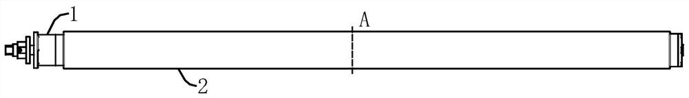
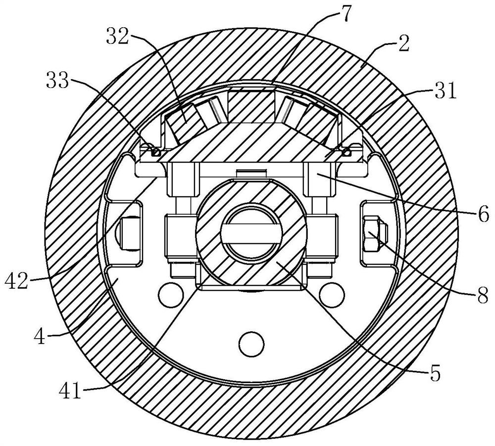
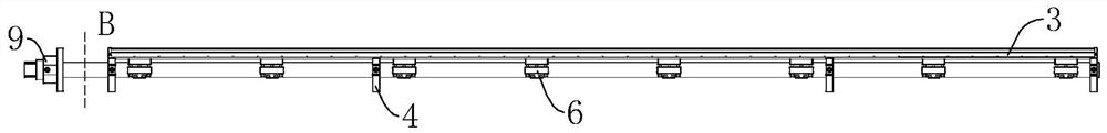
[0038] Such as Figure 1-4 As shown, the present application provides a magnetron 1 for implementing magnetron sputtering, which includes a cylindrical target material 2. The inside of the target material 2 serves as an installation chamber and is provided with a cathode magnet 3, and the installation chamber is along the target material. 2 A plurality of support frames 4 are arranged at intervals in the axial direction, and cooling water pipes 5 extending in the axial direction of the target 2 are fixed on the plurality of support frames 4;

[0039] The cathode magnet bar 3 includes a pole shoe 31 extending in the axial direction of the target 2 and a plurality of magnetic blocks 32 fixed on the top surface of the pole shoe 31. The top surface is also buckled with a sealing cover 7 for shielding the magnetic blocks 32.

[0040] In this embodiment, the magnetron sputtering coating needs to work at a very high power, so that the entire magnetron 1 will be in a higher temperature sta...


PUM


Abstract

The invention relates to a magnetron tube for carrying out magnetron sputtering. The magnetron tube for carrying out magnetron sputtering comprises a barrel-shaped target. The interior of the target serves as a mounting chamber and is provided with a cathode magnetic bar, multiple supporting frames are arranged on the mounting chamber in the axial direction of the target at intervals, and coolingwater pipes stretching in the axial direction of the target are fixed to the multiple supporting frames. The cathode magnetic bar comprises a pole shoe stretching in the axial direction of the targetand multiple magnetic blocks fixed to the top face of the pole shoe. The bottom face of the pole shoe is connected with the cooling water pipes through interval adjusting seats, and a sealing cover for shielding all the magnetic blocks is further buckled on the top face of the pole shoe. Through the arrangement of the interval adjusting seats, the intensity of the magnetic field reaching the target can be adjusted, the sealing cover is arranged on the top face of the pole shoe, and therefore it is guaranteed that magnets work under the condition of water isolation. By the adoption of the magnetron tube, the service life of the magnetron tube can be prolonged, and the coating quality can be improved.

Description

Technical field [0001] The present invention relates to the field of magnetron sputtering coating technology, in particular to a magnetron used for magnetron sputtering. Background technique [0002] The types of magnetron sputtering target installation targets are divided into planar magnetron sputtering devices and cylindrical magnetron sputtering devices. For cylindrical magnetron sputtering devices, the magnetic field is very important for the sputtering deposition process. Magnetron sputtering is based on two-stage sputtering, introducing a magnetic field on the surface of the target, and using the magnetic field to restrict the movement of charged particles to increase the density of the plasma and achieve a high sputtering rate. . However, since the intensity of the magnetic field generated by each magnet block is different from the expected intensity, how to ensure the uniform distribution of the magnetic field intensity on the target surface in the effective coating ar...

Claims


Application Information

Patent Timeline
IPC IPC(8): C23C14/35
CPCC23C14/3407C23C14/35
Inventor 来华杭俞峰刘杰施成亮江嘉周海龙
Owner ZHEJIANG SHANGFANG ELECTRONICS EQUIP
Why Eureka
Try Eureka