
Magnet control system for magnetron sputtering device

A magnetron sputtering and control system technology, applied in sputtering coating, discharge tube, vacuum evaporation coating, etc., can solve the problem of excessive operating time, increased manufacturing costs, and the adjustment of magnetic field strength cannot be locally formed, etc. problem, achieve the effect of improving in-plane distribution and preventing local excessive erosion

Active Publication Date: 2019-08-16
ULVAC KOREA
View PDF14 Cites 0 Cited by
  • Summary
  • Abstract
  • Description
  • Claims
  • Application Information

AI Technical Summary

Problems solved by technology

However, these methods all increase the manufacturing cost, and the intensity of the magnetic field is adjusted by hand, and the adjustment of the magnetic field intensity cannot be formed locally, so there are problems such as requiring repeated operations several times, and much work time.

Method used


Image

  • Magnet control system for magnetron sputtering device
  • Magnet control system for magnetron sputtering device
  • Magnet control system for magnetron sputtering device

Examples


Embodiment

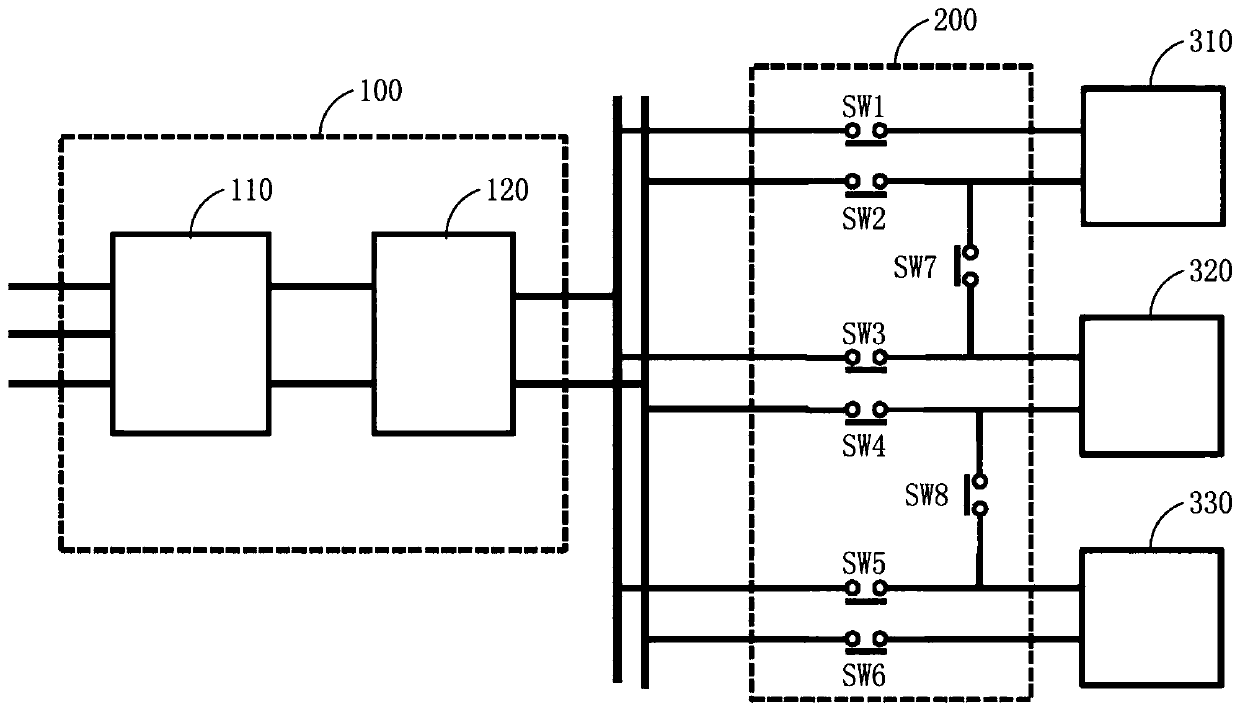
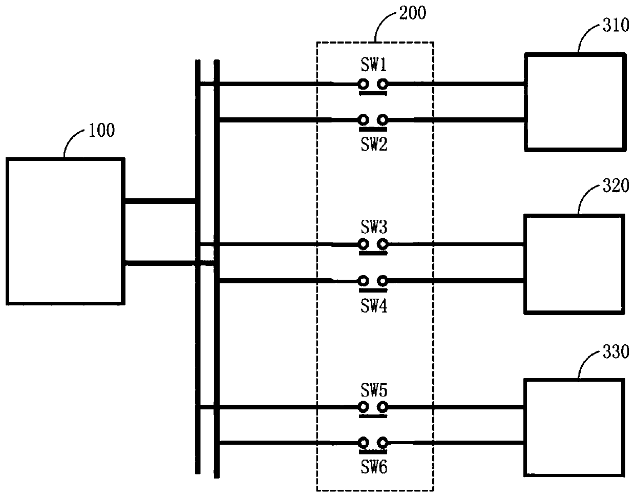
[0130] Figure 7a to Figure 7d It is shown that as an embodiment of the present invention, a magnet unit including a plurality of magnet structures such as Figure 5b A schematic diagram of the structure of the magnet structure connected after a part or the entire magnet assembly is connected to the drive power supply unit using a switch.

[0131] As an example of the present invention, a plurality of magnet structures including T-shaped permanent magnets and coiled permanent magnet wires were produced. connection arrangement of the magnet structures, forming as Figure 5b magnet unit. A switch is used to selectively apply current to a part or all of the magnet combination, and the magnetic field strength at the center of the first magnet group and the second magnet group is measured.

[0132] Figure 7a is a picture showing the configuration of the magnet unit for measuring the magnetic field strength constituted and for measuring the magnetic field strength, and Figure...


PUM


Abstract

The present invention relates to a system, for controlling a magnet, which can be used for a magnetron sputtering device. A magnet control system for a magnetron sputtering device of the present invention comprises: a driving power unit; a magnetism generation unit comprising a plurality of magnet arrays; and a magnetism control unit comprising a switch for controlling one or more of the pluralityof magnet arrays such that the magnet arrays can be selectively connected to the driving power unit.

Description

technical field [0001] The present invention relates to a control magnet system and the like that can be used in a magnetron sputtering device, and relates to a magnet control system for controlling a magnetron sputtering device connected between a plurality of magnet structures. Background technique [0002] A sputtering device is a device for coating thin films on substrates when manufacturing semiconductors, FPDs (LCDs, OLEDs, etc.) or solar cells. In addition, sputtering devices can also be used in roll-to-roll devices. A magnetron sputtering (magnetron sputtering) device in the sputtering device uses the gas injected into the lead chamber (chamber) in a vacuum state to generate plasma, and the ionized gas particle ions and the target material to be plated After the collision, the technology of plating the particles sputtered by the collision on the substrate. In this case, the magnetic field lines are formed in the future, and the magnet unit faces the substrate and i...

Claims


Application Information

Patent Timeline
Patent Type & Authority Applications(China)
IPC IPC(8): H01J37/34C23C14/35
CPCC23C14/35H01J37/34H01J37/3461H01J37/3455
Inventor 金正健苏秉镐全明雨高武昔李九铉
Owner ULVAC KOREA
Learn More