
Subway underground long and longitudinal structure concrete temperature stress anchoring system

A technology of concrete temperature and temperature stress, applied in underground chambers, earthwork drilling, wellbore lining, etc., can solve the problem of failure to achieve long and longitudinal structure cracking and leakage, failure to reduce the accumulation of temperature stress, and failure to set deformation joints in stations and other problems to avoid structural cracking, improve crack resistance, and improve stiffness.

Active Publication Date: 2020-10-27
CHINA POWER CONSTR SOUTHERN CONSTR INVESTMENT CO LTD +3
View PDF6 Cites 0 Cited by
  • Summary
  • Abstract
  • Description
  • Claims
  • Application Information

AI Technical Summary

Problems solved by technology

However, due to the functional requirements of the subway operation, deformation joints (including expansion joints and settlement joints) cannot be set in the station
Therefore, in view of the temperature stress change of the concrete structure caused by the annual temperature difference in the long longitudinal structure, the existing technology cannot effectively restrain the shrinkage generated inside the structure, nor can it reduce the accumulation of temperature stress, and fail to suppress the cracking and seepage of the long longitudinal structure. The purpose of the leak

Method used


Image

  • Subway underground long and longitudinal structure concrete temperature stress anchoring system
  • Subway underground long and longitudinal structure concrete temperature stress anchoring system
  • Subway underground long and longitudinal structure concrete temperature stress anchoring system

Examples


Embodiment Construction

[0041] In order to make the technical problems, technical solutions and beneficial effects to be solved by the present invention clearer, the present invention will be further described in detail below in conjunction with the accompanying drawings and embodiments. It should be understood that the specific embodiments described here are only used to explain the present invention, not to limit the present invention.

[0042] It should be noted that when a component is referred to as “fixing” or “setting” or “connecting” another component, it may be directly or indirectly located on the other component. The orientations or positions indicated by the terms "front", "rear", "top", "bottom", "inner" and "outer" are based on the orientations or positions shown in the drawings, and are for convenience of description only, and cannot be interpreted as Restrictions on this technical solution. "Several" means one or more than one, unless otherwise clearly and specifically defined.

[0...


PUM


Abstract

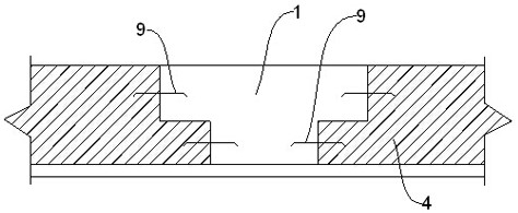
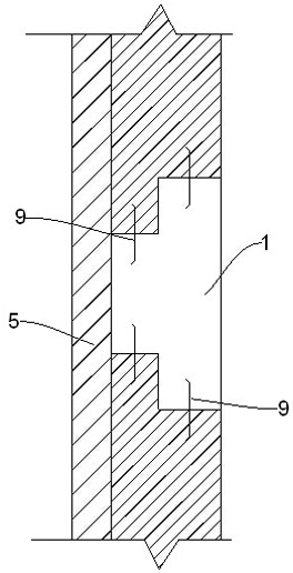
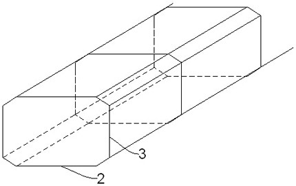
The invention discloses a subway underground long and longitudinal structure concrete temperature stress anchoring system. Multiple transverse temperature stress post-cast strips and multiple sets ofanchoring structures are arranged in the longitudinal direction of an underground long and longitudinal structure, the anchoring structures comprise anchoring beams and anchoring columns, and the anchoring beams and the anchoring columns are connected end to end to form a closed framework. The T-shaped temperature stress post-cast strips are adopted, the contact area of the temperature stress post-cast strips and concrete is increased, pouring is carried out at the annual low temperature time, anti-cracking capacity is improved, and the structure temperature during closing of the long and longitudinal structure is reduced; the anchoring columns are arranged on the two sides to be anchored with an underground diaphragm wall of an envelop structure; the anchoring beams are arranged to be anchored with a rock soil layer, the closed framework is formed by the anchoring beams and the anchoring columns, anti-cracking steel bars are densified, rigidity is improved, the temperature differenceaffected length is reduced, the influence of temperature stress on the long and longitudinal structure is reduced, and structural cracking caused to the long and longitudinal structure due to temperature stress is avoided; and the overall structure is simple, and the body structure is not influenced.

Description

technical field [0001] The invention relates to the technical field of construction engineering, and more specifically relates to a concrete temperature stress anchoring system for underground long longitudinal structures of subways. Background technique [0002] The subway project is an important municipal transportation project in a modern city. It carries the important task of urban residents with a large passenger flow, and its project quality is a century-old project. [0003] In underground projects such as subways, the main waterproof parts of the concrete main structure are the bottom plate, side walls and roof. These parts consider the structural force, economy and clearance requirements of the track area, and basically adopt the one-way slab design, with a length of more than 200 meters. , part of the length is more than 500m, the main structure is poured in sections, and its full length is closed to form a single slab structure with a length of more than 200m, res...

Claims


Application Information

Patent Timeline
IPC IPC(8): E21D11/10E21D11/38
CPCE21D11/10E21D11/107E21D11/38
Inventor 杨骏张宏伟刘文丽罗云松
Owner CHINA POWER CONSTR SOUTHERN CONSTR INVESTMENT CO LTD
Learn More