High-pressure pump

A high-pressure pump and pump body technology, which is applied in the fields of high-pressure cleaning pumps, mine emulsion pumps, and high-pressure pumps, and can solve problems such as fast wear, small contact area, and high pressure.

Pending Publication Date: 2020-10-27
无锡迅元精密科技有限公司
View PDF0 Cites 0 Cited by
  • Summary
  • Abstract
  • Description
  • Claims
  • Application Information

AI Technical Summary

Problems solved by technology

When the cylindrical cam is working, the radial bearing and the cam groove are in point or line contact, and the contact area is small, resulting in greater pressure and faster wear under the same pressure
Therefore, the service life of this high-pressure pump is relatively short
Moreover, due to faster wear and tear, this high-pressure pump needs to control the maximum speed, resulting in lower pump water pressure

Method used


Image

  • High-pressure pump
  • High-pressure pump
  • High-pressure pump

Examples


Embodiment Construction

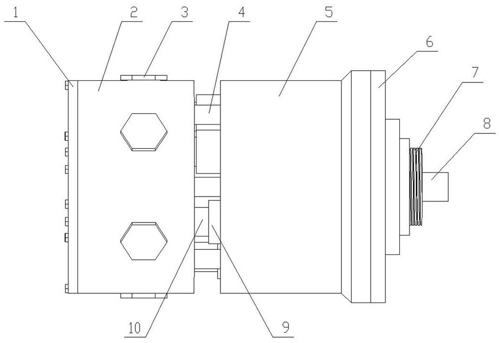
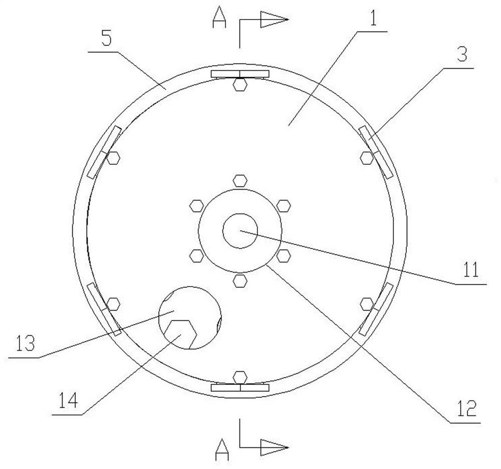
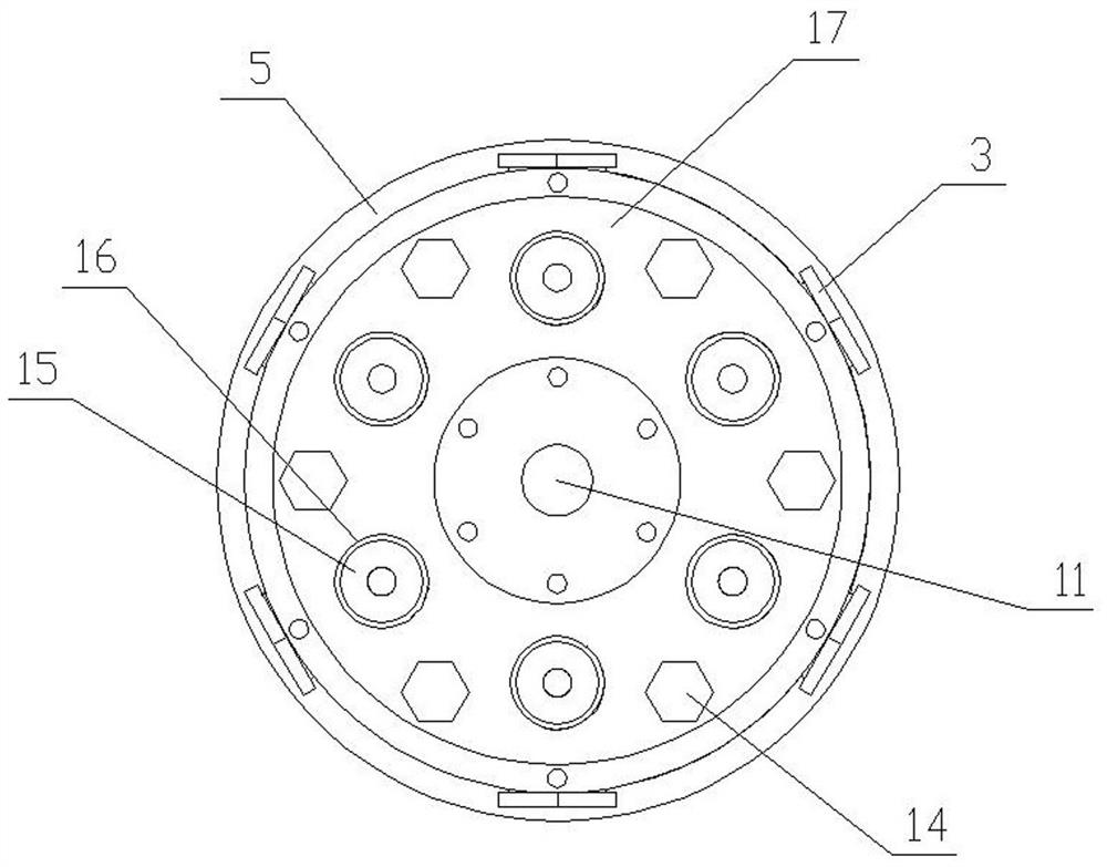
[0023] The present invention will be described in further detail below in conjunction with the accompanying drawings.

[0024] Such as Figure 1~7 As shown, the high-pressure pump of the present invention includes a pump head 2 and a cylindrical pump body 5 , the pump head 2 is connected to the pump body 5 , and the bottom of the pump body 5 faces the pump head 2 . The cylinder bottom of the pump body 5 is uniformly distributed with piston rods along its circumference, and the piston rods are all arranged axially along the pump body 5. The two ends of the piston rod protrude from the two sides of the cylinder bottom of the pump body 5 respectively. The pump body 5 fits in a sliding and sealed manner, and one end of the piston rod outside the pump body 5 is connected to the pump head 2 . The pump body 5 is concentrically provided with a rotating shaft 8, and the rotating shaft 8 and the pump body 5 are in a rotating fit, and a swash plate 23 is fixed on the rotating shaft 8, a...


PUM


Abstract

The invention relates to general machinery, in particular to a high-pressure pump. The pump comprises a pump head and a barrel-shaped pump body. The pump head is connected with the pump body, and thebarrel bottom of the pump body faces the pump head. Piston rods are evenly distributed at the barrel bottom of the pump body in the circumferential direction of the barrel bottom and arranged in the axial direction of the pump body. The two ends of each piston rod stretch out of the two sides of the barrel bottom of the pump body respectively, the piston rods are in sliding sealing fit with the pump body, and the portions, located outside the pump body, of one ends of the piston rods are connected with the pump head. The pump is characterized in that a rotating shaft is concentrically arrangedin the pump body, the rotating shaft is matched with the pump body in a rotating mode, a swash plate is fixed to the rotating shaft, notches are formed in the sections, located in the pump body, of the the inner side walls of the piston rods, the piston rods are clamped to the swash plate through the notches, and gaps are formed between the outer edge of the swash plate and the bottoms of the notches. Ball heads are arranged on the portions, in the notches, of the two end faces of the swash plate. Flat plates are arranged on the sides, corresponding to the ball heads, of the swash plate and abut against the swash plate. The high-pressure pump is long in service life and high in water pumping pressure.

Description

technical field [0001] The present invention relates to a general machine, in particular to a high pressure pump for pumping liquid. It is especially suitable for high-pressure cleaning pumps and mine emulsion pumps. Background technique [0002] The Chinese patent application number 2019215277049 discloses a high-pressure pump. It mainly includes pump head and casing. There is a cylindrical cam inside the casing, and the cylindrical cam and the casing are axially fixed and circumferentially rotated. A piston rod is arranged in the casing outside the cylindrical cam along the circumferential direction of the cylindrical cam, and the piston rods are all along the axial direction of the cylindrical cam. Arrangement, one end of the piston rod protrudes through the housing, and the piston rod and the housing are in a movable fit along the axial direction of the piston rod. One side of the position block is located in the cam groove of the cylindrical cam, and a radial bearing...

Claims


Application Information

Patent Timeline
Patent Type & Authority Applications(China)
IPC IPC(8): F04B1/146F04B1/124F04B1/141
CPCF04B1/124F04B1/141F04B1/146
Inventor 陈阳
Owner 无锡迅元精密科技有限公司
Why Eureka
Try Eureka