
High-frequency hydraulic vibration exciter

A hydraulic vibration exciter and high-frequency technology, which is applied in fluid pressure actuation devices, fluid pressure actuation system components, mechanical equipment, etc., can solve the problems of high energy consumption of hydraulic vibration excitation equipment, high energy consumption systems, and low efficiency

Active Publication Date: 2020-10-27
ZHEJIANG UNIV CITY COLLEGE
View PDF17 Cites 0 Cited by
  • Summary
  • Abstract
  • Description
  • Claims
  • Application Information

AI Technical Summary

Problems solved by technology

In recent years, hydraulic vibration technology has developed rapidly, but hydraulic vibration equipment consumes a lot of energy and has low efficiency. In addition to the two energy conversions of mechanical energy and pressure energy, most of the existing hydraulic vibration equipment is controlled by hydraulic reversing valves. Working in the mode of hydraulic cylinder, this is essentially a throttling and speed regulating circuit, which is a high energy consumption system

Method used


Image

  • High-frequency hydraulic vibration exciter
  • High-frequency hydraulic vibration exciter
  • High-frequency hydraulic vibration exciter

Examples


Embodiment approach

[0046] The high-frequency hydraulic vibration exciter of the present invention is suitable for hydraulic vibration systems, such as Figure 17 As shown, it includes DC motor controller C, motor C1, coupling C2, hydraulic pump C3, hydraulic oil tank C4, pilot relief valve C5, pressure gauge C6, pressure sensor C7, data acquisition system C8 and computer C9. The hydraulic pump C3 is a one-way quantitative hydraulic pump, and the main shaft of the electric motor C1 is coaxially connected with the main shaft of the hydraulic pump C3 through a coupling C2. The oil suction port of the hydraulic pump C3 is directly connected to the hydraulic oil tank C4, the outlet of the hydraulic pump C3 is bypassed in parallel with the pilot relief valve C5, the outlet of the pilot relief valve C5 is directly connected to the hydraulic oil tank C4, and the main oil circuit of the hydraulic pump C3 is directly connected to the high-frequency hydraulic excitation The high-pressure oil port Y13 of th...


PUM


Abstract

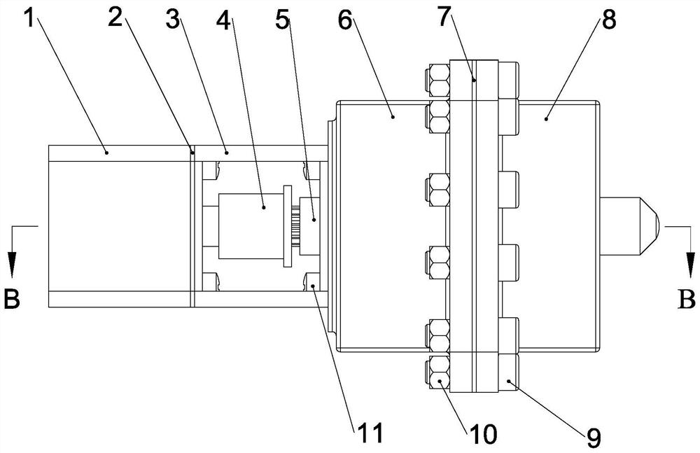
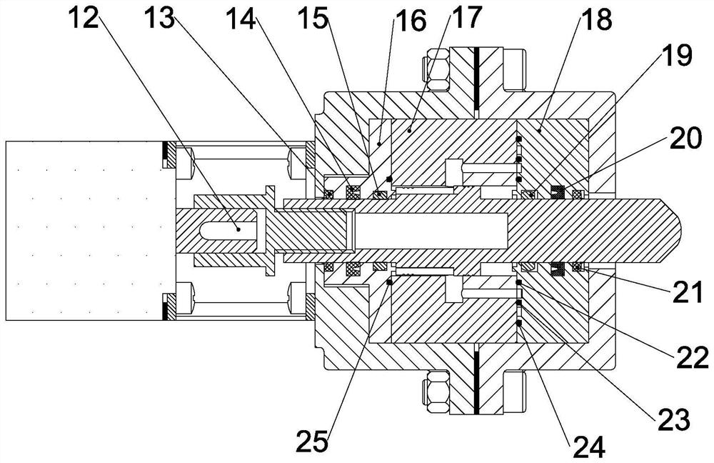
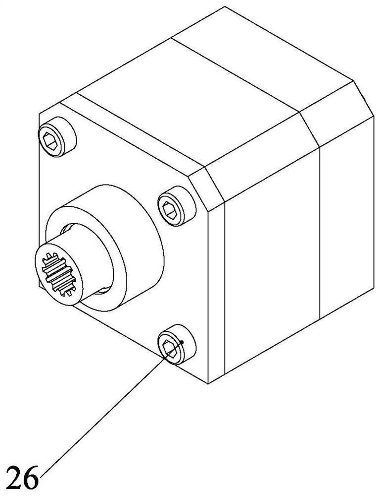
The invention provides a high-frequency hydraulic vibration exciter. The high-frequency hydraulic vibration exciter consists of a valve body, a valve core, safety covers, a transmission shaft and an electromechanical converter, wherein the valve core is provided with a shoulder; eight axial oil grooves in two groups are uniformly distributed and machined on the shoulder; eight radial oil holes intwo groups are formed in the valve body, when the high-frequency hydraulic vibration exciter works, the axial oil grooves and the radial oil holes are periodically connected and disconnected; in the two groups of radial oil holes in the valve body, one group of radial oil holes communicate with a high-pressure oil passage, and the other group of radial oil holes communicate with a lower-pressure oil passage; and when the valve core rotates under the driving of the electromechanical converter and the transmission shaft, the pressure on the left end face and right end face of the shoulder of thevalve core alternates between high pressure and low pressure through the radial oil holes in the valve body and the axial oil grooves in the valve core, so that the valve core is driven to axially reciprocate to realize the high-frequency vibration. The high-frequency hydraulic vibration exciter is mainly characterized in that the axial movement frequency of the valve core is high, the movement frequency is automatically controlled by the electromechanical converter, and the structure is compact; and the high-frequency hydraulic vibration exciter can be used as an actuating element for occasions with high requirements on working frequency such as the hydraulic vibration.

Description

technical field [0001] The invention relates to a high-frequency hydraulic vibration exciter, which belongs to the technical field of hydraulic components. Background technique [0002] Vibration measurement and vibration experiment analysis are widely used in mechanical engineering and engineering structure departments, such as vibration transmission, vibrating screen, vibrating mixer, mechanical hammer and so on. Commonly used exciters are electric, electromagnetic and electro-hydraulic. The advantages of the electro-hydraulic exciter are large excitation force and large stroke. And because the power-to-weight ratio of the electro-hydraulic vibrator is large, the vibration equipment can be miniaturized and lightened, so it is more suitable for mobile equipment than mechanical and electromagnetic vibration exciters. In recent years, hydraulic vibration technology has developed rapidly, but hydraulic vibration equipment consumes a lot of energy and has low efficiency. In a...

Claims


Application Information

Patent Timeline
Patent Type & Authority Applications(China)
IPC IPC(8): F15B21/12
CPCF15B21/12F15B21/125
Inventor 陆倩倩邵威夏春林
Owner ZHEJIANG UNIV CITY COLLEGE
Learn More