Clamp for zirconium pipe fatigue test and test method
A technology of fatigue test and test method, which is applied in the field of component fatigue test, and can solve problems such as high-temperature clamping technology of thin-walled tubes
- Summary
- Abstract
- Description
- Claims
- Application Information
AI Technical Summary
Problems solved by technology
Method used
Image
Examples
Embodiment 1
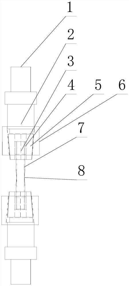
[0038] Such as figure 1 and figure 2 As shown, a fixture that can be used for the zirconium tube fatigue test, the fixture includes a clamping part for providing clamping constraints on the end of the tubular test piece 7, and also includes a clamping part for filling in the test piece 7 The inner plug head 3 in the end and the tube gasket 4 used to wrap the outside of the end of the test piece 7, the materials of the inner plug head 3 and the tube gasket 4 are soft thermal expansion materials.
[0039] Taking the zirconium tube as the fuel rod casing as an example, since its working environment is in a high temperature environment, for the high cycle fatigue test of its life under high temperature conditions, 1×10 7 Taking the second life as an example, it takes 28 hours to use 100HZ frequency, and 280 hours to use 10HZ frequency. However, since the test piece 7 that is directly the zirconium tube part itself or the test piece 7 that is scaled down according to the zirconi...
Embodiment 2
[0043] The present embodiment is further limited on the basis of embodiment 1, as figure 1 and figure 2 As shown, considering the influence of the thermal deformation of the thermal expansion material on the deformation of the end of the test piece 7, to avoid excessive deterioration of the mechanical properties of the end of the test piece 7 due to excessive extrusion of the thermal expansion material, the setting is: the thermal expansion The material is copper or copper alloy.
[0044] In order to facilitate the close fit between the inner plug head 3 and the inner wall of the test piece 7, minimize the amount of extrusion deformation of the test piece 7 during the clamping process and during the test, the inner wall of the test piece 7 and the inner plug head 3 are in high frequency The possibility of collision under the action, to avoid the end of the test piece 7 from breaking during the experiment, is set as follows: the inner plug head 3 is a tapered columnar structu...
Embodiment 3
[0055] Such as figure 1 As shown, this embodiment also discloses a test method that can be used for the zirconium tube fatigue test. The test method adopts two clamps that are respectively clamped on different ends of the test piece 7, and the clamps are used as intermediate connectors to complete the test method. The test piece 7 is connected to the testing machine, and then the testing machine is turned on to complete the fatigue test of the test piece 7. The clamp is the clamp provided by any one of the above embodiments. As mentioned above, the present test method is based on the jig, so that the high cycle fatigue test can be applied to the thin-walled test piece 7 which is a zirconium tube or the thin-walled test piece 7 which is a zirconium tube simulation body.
[0056] As a further technical solution of the test method: in the axial direction of the test piece 7, it also includes an annular groove 8 arranged outside the test piece 7 and extending along the circumferen...
PUM
 Abstract
Description
Claims
Application Information
 - R&D
- Intellectual Property
- Life Sciences
- Materials
- Tech Scout
- Unparalleled Data Quality
- Higher Quality Content
- 60% Fewer Hallucinations
Browse by: Latest US Patents, China's latest patents, Technical Efficacy Thesaurus, Application Domain, Technology Topic, Popular Technical Reports.
© 2025 PatSnap. All rights reserved.Legal|Privacy policy|Modern Slavery Act Transparency Statement|Sitemap|About US| Contact US: help@patsnap.com


