Cable with Z-shaped shielding layer

A technology of shielding tape and conductive layer, applied in the direction of power cable, insulated cable, power cable with shielding layer/conductive layer, etc., can solve the problems of gap and discontinuity in the shielding layer

Pending Publication Date: 2020-10-27
优易电缆(张家港)有限公司
View PDF0 Cites 0 Cited by
  • Summary
  • Abstract
  • Description
  • Claims
  • Application Information

AI Technical Summary

Problems solved by technology

[0007] The purpose of this application is to provide a shielding tape, which can be applied to cables to solve the problem of gaps and discontinuity in the shielding layer in the prior art

Method used


Image

  • Cable with Z-shaped shielding layer
  • Cable with Z-shaped shielding layer
  • Cable with Z-shaped shielding layer

Examples


Embodiment 1

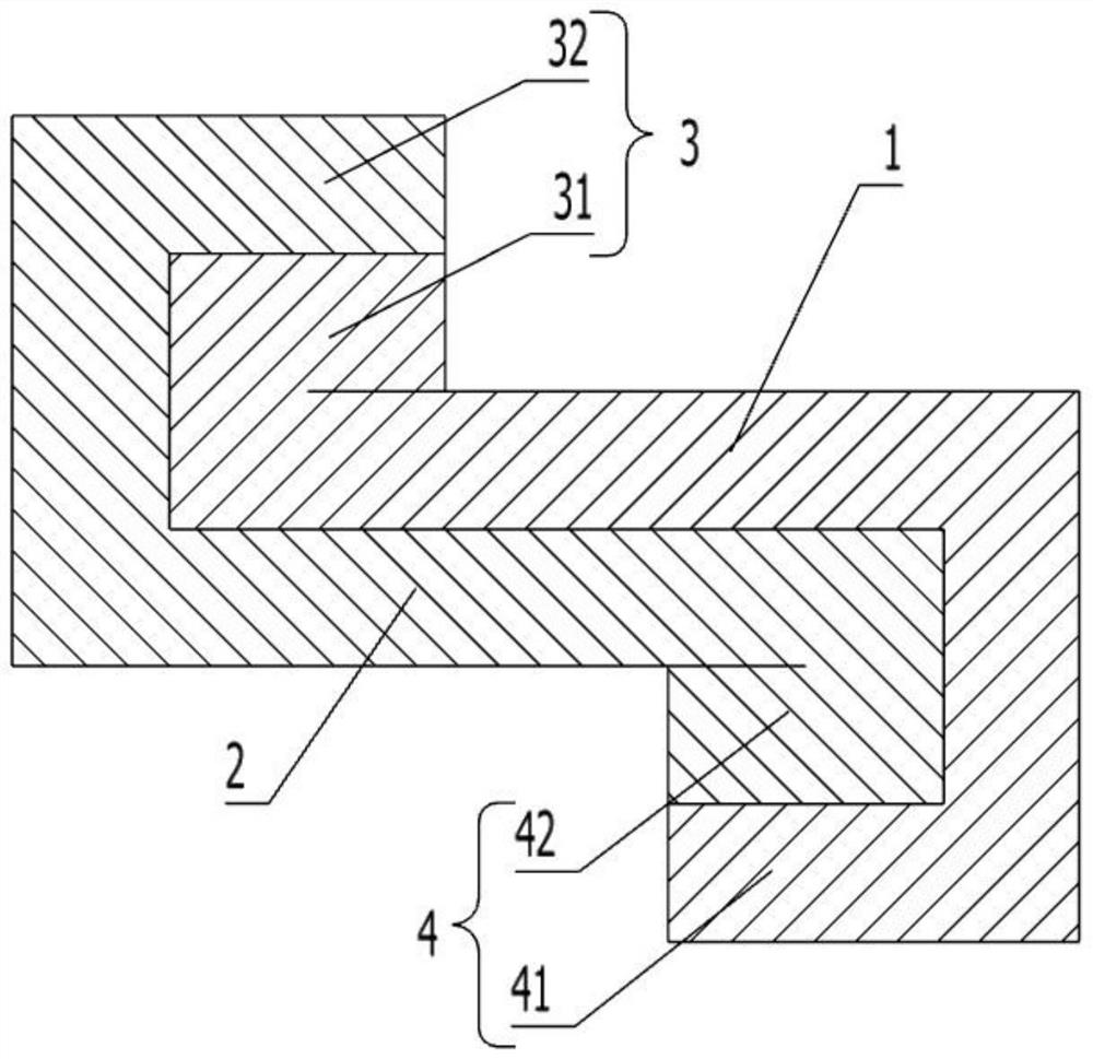
[0066] figure 1 It is a schematic cross-sectional view of a shielding tape in this application, image 3 It is a schematic diagram of a cable structure in this application, image 3 yes figure 1 Schematic diagram of the application scenario of the shielding tape in . refer to figure 1 and image 3 This embodiment provides a shielding tape, which is used as a shielding layer of a cable, and includes a first conductive layer 1 and an insulating layer 2, and the first conductive layer 1 and the insulating layer 2 can be fixed by glue. Among them, in this embodiment, the shielding tape is provided with a first fold 3 and a second fold 4 on both sides of the shielding tape, the first fold 3 is formed by folding the shielding tape toward the first conductive layer 1 side, and the second fold Edge 4 is formed by folding the shielding tape toward the insulating layer 2, making the shielding tape Z-shaped. When the shielding tape is wrapped around the outside of the core wire, the...

Embodiment 2

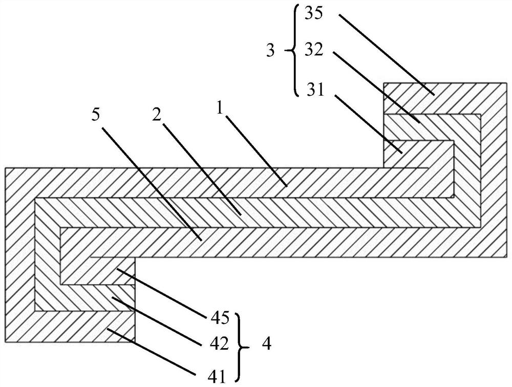
[0071] figure 2 is a schematic cross-sectional view of another shielding tape in this application, image 3 It is a schematic diagram of a cable structure in this application, image 3 yes figure 2 Schematic diagram of the application scenario of the shielding tape in . refer to figure 2 and image 3 , this embodiment provides a shielding tape, including a first conductive layer 1, an insulating layer 2 and a second conductive layer 5, the first conductive layer 1 and the second conductive layer 5 are arranged on both sides of the insulating layer 2, the first The conductive layer 1 and the insulating layer 2 , and the second conductive layer 5 and the insulating layer 2 can be fixed by glue. Among them, in this embodiment, the shielding tape is provided with a first folded edge 3 and a second folded edge 4 on both sides of the shielding tape. The first folded edge 3 is formed by folding the shielding tape toward the first conductive layer 1 side. The edge 4 is formed...

Embodiment 3

[0076] image 3 It is a schematic diagram of a cable structure in this application, Figure 4 yes image 3 Partial enlarged view of A, Figure 5 It is a schematic cross-sectional structure diagram of this embodiment.

[0077] refer to Figure 3-5 This embodiment provides a cable, including a core wire 100, a shielding body 200 and a sheath layer 300 arranged outside the core wire 100, and the shielding body 200 further includes a shielding layer 210 and a braided mesh 220. Wherein, the shielding layer 210 is made of a shielding tape, preferably an aluminum foil tape, which can be single-sided aluminum foil or double-sided aluminum foil. The shielding layer 210 is wrapped around the outside of the core wire 100 by winding or wrapping, and has an inner edge 211 and an outer edge 212 at its joint, the inner edge 211 is turned outward, and the outer edge 212 is turned outward.

[0078] In this embodiment, the inner edge 211 and the outer edge 212 are in contact with each othe...


PUM


Abstract

The invention discloses a cable with a Z-shaped shielding layer, and relates to the technical field of cable shielding and transmission. According to the technical scheme, the cable comprises a core wire, a shielding body and a sheath layer, wherein the shielding body is arranged on the outer side of the core wire, and the shielding body comprises a shielding layer; the sheath layer is arranged onthe outer side of the shielding body; the shielding layer is provided with an inner edge and an outer edge; the inner edge is folded outwards; and the outer edge is folded inward. According to the invention, the inner and outer edges of the shielding layer are folded, mutual contact between the inner edge and the outer edge is realized, and a conductive layer on the inner edge is communicated with a conductive layer on the outer edge, so that the conductive layer of the whole shielding layer forms a continuous whole, the shielding layer can form a complete shielding body, the problem that gaps exist in the shielding layer in the prior art is solved, electromagnetic leakage of the cable is avoided, and the EMC characteristic of the cable is improved.

Description

technical field [0001] The present application relates to the technical field of cable shielding and transmission, in particular to a cable with a Z-shaped shielding layer. Background technique [0002] The shielded wiring system is to add a metal shielding layer on the outside of the ordinary unshielded system, using the reflection, absorption and skin effect of the metal shielding layer (the so-called skin effect means that the distribution of current in the conductor cross section tends to tend to Conductor surface distribution, the higher the frequency, the smaller the skin depth, that is, the higher the frequency, the weaker the penetration ability of electromagnetic waves) to achieve the function of preventing electromagnetic interference and electromagnetic radiation. The shielding system comprehensively utilizes the balance principle of the twisted pair and the shielding effect of the shielding layer, so it has a certain electromagnetic compatibility (EMC, which mean...

Claims


Application Information

Patent Timeline
IPC IPC(8): H01B7/17H01B13/22H01B9/02
CPCH01B7/17H01B9/021H01B13/22
Inventor 李金涛齐刚俞俊
Owner 优易电缆(张家港)有限公司
Why Eureka
Try Eureka