Lead wire bracket structure for increasing creepage distance

A technology of lead bracket and creepage distance, which is applied to the parts of transformer/inductor, transformer/inductor coil/winding/connection, circuit, etc., and can solve the problem of tight creepage distance of lead wire

Pending Publication Date: 2020-10-27
TBEA SHENYANG TRANSFORMER GRP CO LTD +1
View PDF5 Cites 0 Cited by
  • Summary
  • Abstract
  • Description
  • Claims
  • Application Information

AI Technical Summary

Problems solved by technology

[0004] In view of the above problems, the object of the present invention is to provide a lead support structure that increases the creepage di

Method used


Image

  • Lead wire bracket structure for increasing creepage distance
  • Lead wire bracket structure for increasing creepage distance
  • Lead wire bracket structure for increasing creepage distance

Examples


Embodiment Construction

[0021] In order to make the object, technical solution and advantages of the present invention clearer, the present invention will be described in detail below in conjunction with the accompanying drawings and specific embodiments.

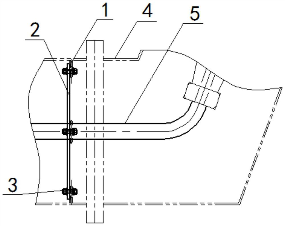
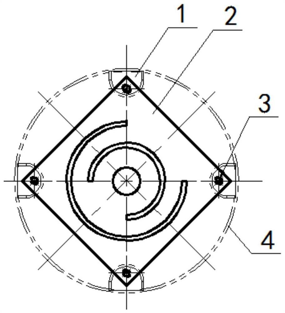
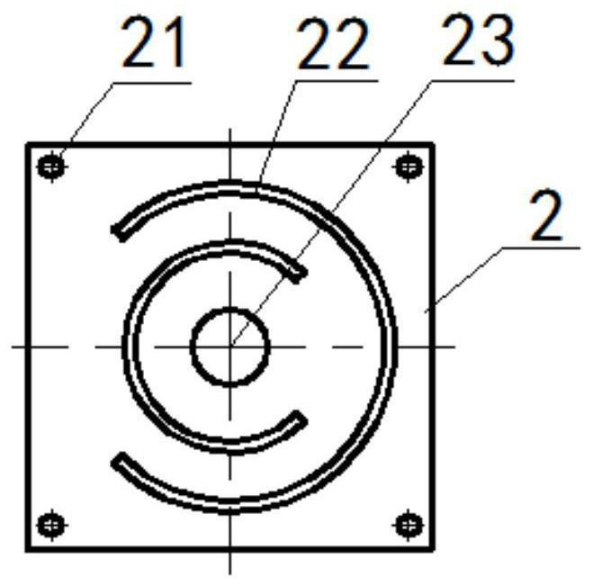
[0022] Such as Figure 1-3 As shown, the present invention provides a lead support structure for increasing the creepage distance, including an insulating plate 2 and a connecting piece, the insulating plate 2 is fixed inside the raised seat 4 through the connecting piece, and the insulating plate 2 is along the radial direction of the raised seat 4 It is provided that the insulating plate 2 is provided with a through hole 23 for the lead wire 5 to pass through.

[0023] The insulating board 2 is cardboard, and the insulating board 2 is provided with a heat dissipation groove 22, and the heat dissipation groove 22 is an arc-shaped structure.

[0024] In the embodiment of the present invention, the cooling groove 22 is a plurality of arcs arranged...


PUM

PropertyMeasurementUnit
Widthaaaaaaaaaa

Abstract

The invention belongs to the technical field of transformer manufacturing, and particularly relates to a lead wire bracket structure capable of increasing a creepage distance. The lead wire bracket structure comprises an insulating plate and a connecting piece, wherein the insulating plate is fixed in an ascending seat through the connecting piece, a through hole for a lead wire to penetrate through is formed in the insulating plate, and the insulating plate is a paperboard, and is provided with a heat dissipation groove. By clamping the lead cable in the ascending seat, the supporting effectis achieved, the heat dissipation function is achieved, and the requirement for the insulation distance is met.

Description

technical field [0001] The invention belongs to the technical field of transformer manufacturing, in particular to a lead support structure for increasing creepage distance. Background technique [0002] During the operation of the transformer, there is current flowing in the lead wire, and there is an electric field force on the lead wire. For a winding with a low voltage level, when the working current is large, the lead wire generally uses copper busbar or copper tube as the first choice; small capacity and low voltage Lead wires of grade transformers often use lead cables, and its electric field conditions are better than those of copper busbars to a certain extent. The lead wires inside the transformer have a fixed potential. In order to ensure the safe operation of the transformer, sufficient safety insulation distance must be considered between the lead wires and the metal components, the oil tank, the same-phase winding, the different-phase winding and the lead wires...

Claims


Application Information

Patent Timeline
IPC IPC(8): H01F27/00H01F27/08H01F27/29H01F27/32
CPCH01F27/00H01F27/08H01F27/29H01F27/324
Inventor 王晓雨苑东升刘均菲
Owner TBEA SHENYANG TRANSFORMER GRP CO LTD
Why Eureka
Try Eureka