Converter station reactive power optimization method considering main transformer low-voltage side reactive power compensation device

A technology of main transformer low-voltage side and compensation device, applied in reactive power compensation, reactive power adjustment/elimination/compensation, circuit devices, etc., can solve problems such as unreasonable use of resources, unintelligent operation, and equipment heating

Active Publication Date: 2020-10-27
中国南方电网有限责任公司超高压输电公司柳州局
View PDF7 Cites 0 Cited by
  • Summary
  • Abstract
  • Description
  • Claims
  • Application Information

AI Technical Summary

Problems solved by technology

[0004] 1. The excess reactive power leads to an increase in the voltage of the AC system
In the case of high-voltage DC system operation, in addition to providing reactive power, the AC filter must also meet the requirements of filtering harmonics and steady-state constant value. After the AC filter is used, it will generally lead to excess reactive power.
The reactive power strategy calculation method that does not consider low capacity and low reactance fails to truly reflect the reactive power exchange between the converter station and the AC system. voltage rise
[0005] 2. Lead to long-distance transmission of reactive power
The reactive power compensation capacity of a single set of AC filter is large, and the voltage adjustment gradient is too large. If too many AC filters are used, the reactive power of the AC system will be excessive, and the excess reactive power will be transmitted to the surrounding plants and stations through the transmission line, resulting in system failure. Co

Method used


Image

  • Converter station reactive power optimization method considering main transformer low-voltage side reactive power compensation device
  • Converter station reactive power optimization method considering main transformer low-voltage side reactive power compensation device
  • Converter station reactive power optimization method considering main transformer low-voltage side reactive power compensation device

Examples


Embodiment

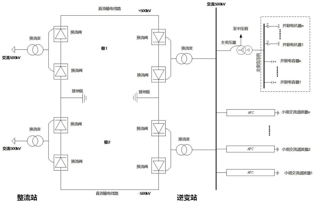
[0080] Taking the inverter station of a ±500kV DC transmission project as an example, the rated transmission power of the converter station is 3200MW, and 12 groups of AC filters are configured on the AC 500kV side, and the rated reactive power compensation capacity of a single group filter is 168Mvar; Transformer, the 35kV side of the main transformer is equipped with (4×60Mvar) low capacity and (6×60Mvar) low reactance, Qcontrol function setting Q exp ∈(-230,0). Table 1 shows the recommended AC filter switching strategy under the bipolar full-voltage operation mode.

[0081] Table 1 Recommended switching strategy of AC filter under bipolar full voltage operation mode of converter station

[0082]

[0083]

[0084] In the table, A stands for A-type AC filter, A-type: DT11 / 24168MVar, that is, tuning times 11, 24, single-group reactive power compensation capacity 168MVar; B stands for B-type AC filter, B-type: TT3 / 13 / 36168MVar, That is, the tuning times are 3, 13, and 3...


PUM


Abstract

The invention discloses a converter station reactive power optimization method considering a main transformer low-voltage side reactive power compensation device, and the method comprises the steps: adding a low capacitor and a low reactor into an option of a reactive power equipment switching strategy, and obtaining a reactive power balance calculation method under the method; optimizing a reactive exchange capacity interval between the converter station and the alternating current system; formulating a strategy of automatically switching reactive power compensation equipment considering a Qcontrol function of low capacitance and low reactance, and modifying control logic in a direct current station control system; realizing the automatic switching of the reactive power compensation device by the Qcontrol function; and when necessary, manually switching low capacity and low reactance for voltage regulation. According to the invention, reactive compensation capabilities of reactive compensation devices with low capacitance, low reactance and the like are utilized in reactive adjustment of the high-voltage direct current system, the reactive adjustment gradient is reduced, and meanwhile, by adjusting the reactive exchange capacity interval of the converter station and the alternating current system, the input group number of alternating current filters is reduced, the resource configuration is optimized, and the voltage control capability is improved.

Description

technical field [0001] The invention relates to the field of high-voltage direct current transmission, in particular to a reactive power optimization method for a converter station taking into account a reactive power compensation device at the low-voltage side of a main transformer. Background technique [0002] HVDC transmission system is a very important energy transmission system in power system. High-voltage direct current transmission is a power transmission method that converts the alternating current generated by the power plant into direct current through the rectifier, and then transmits it to the receiving end through the direct current line, and then uses the inverter to convert the direct current into alternating current and sends it to the receiving end AC power grid. The high-voltage DC system needs to consume a lot of reactive power when it is running. Taking the thyristor converter valve as an example, the reactive power consumed by the thyristors of a singl...

Claims


Application Information

Patent Timeline
IPC IPC(8): H02J3/18H02J3/36
CPCH02J3/1864H02J3/36Y02E40/30Y02E60/60
Inventor 黄松强夏谷林王荣超黄聪杨海亮孙上元章功辽石万里姚日斌张伟陈明佳
Owner 中国南方电网有限责任公司超高压输电公司柳州局
Why Eureka
Try Eureka