Mobile temporary communication base station for construction site

A technology for construction sites and communication base stations, which is applied in the field of mobile temporary communication base stations for construction sites, can solve the problems of large size and inconvenient movement of communication base stations, and achieves the effects of convenient fixing and convenient operation.

Pending Publication Date: 2020-10-27
四川蓉府天悦科技有限公司
View PDF0 Cites 0 Cited by
  • Summary
  • Abstract
  • Description
  • Claims
  • Application Information

AI Technical Summary

Problems solved by technology

[0004] The purpose of the present invention is to provide a mobile temporary communication base station for a construction site. The bottom corner of the shelter body is provided with a support wheel set to facilitate the movement of the temporary communication base station. In addition, the support wheel set can be opened

Method used


Image

  • Mobile temporary communication base station for construction site
  • Mobile temporary communication base station for construction site
  • Mobile temporary communication base station for construction site

Examples


Embodiment 1

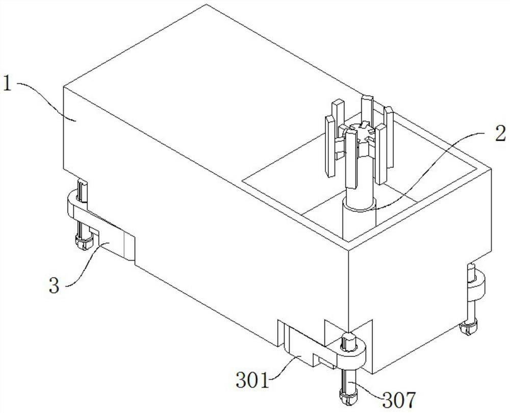
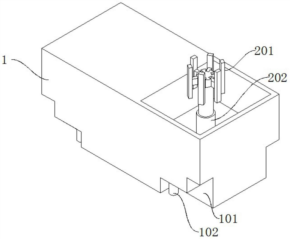
[0033] see Figure 1-6 As shown, the present invention is a mobile temporary communication base station for a construction site, which includes a shelter body 1 and a supporting wheel set 3. The interior of the shelter body 1 is divided into a first cabin and a second cabin, wherein the first cabin is equipped with a communication Monitoring equipment, a signal antenna 2 is installed in the cabin body 2, L-shaped slots 101 are provided at the four bottom corners of the shelter body 1, and a rotating shaft 102 is vertically arranged on a horizontal plane of each L-shaped slot body 101 ;

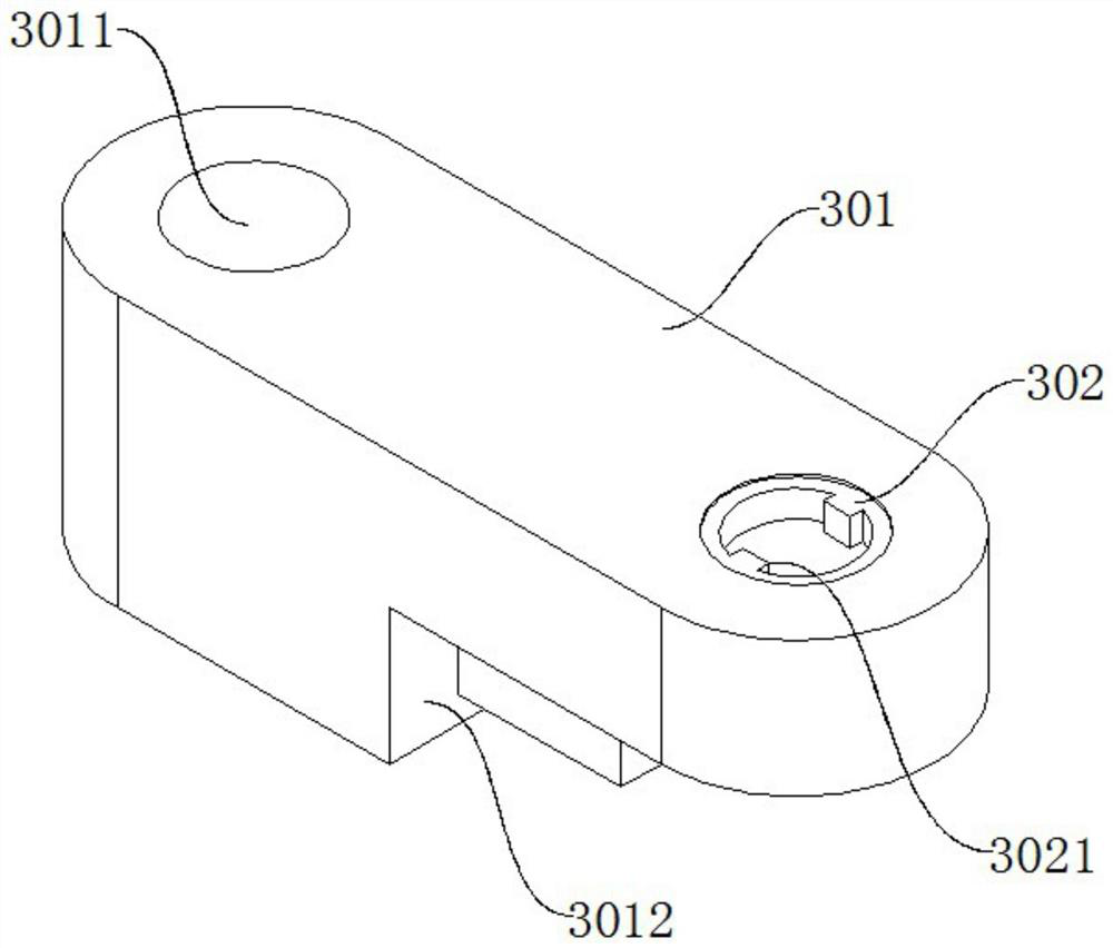
[0034] The supporting wheel set 3 is mainly composed of a rotating arm 301, a limit ring 302, a motor 303, a bevel gear 1 304, a bevel gear 2 305, a bearing 306, a threaded rod 306 and a roller 308;

[0035] Wherein, the shaft hole 3011 provided at one end of the rotating arm 301 is installed in cooperation with the rotating shaft 102, and at the same time, the other end of the rotating arm 3...

Embodiment 2

[0046] see Figure 2-7 As shown, the present invention is a mobile temporary communication base station for a construction site, which includes a shelter body 1 and a supporting wheel set 3. The interior of the shelter body 1 is divided into a first cabin and a second cabin, wherein the first cabin is equipped with a communication Monitoring equipment, a signal antenna 2 is installed in the cabin body 2, L-shaped slots 101 are arranged at the four bottom corners of the shelter body 1, and a rotating shaft 102 is vertically arranged on a horizontal plane of each L-shaped slot body 101 ;

[0047] The supporting wheel set 3 is mainly composed of a rotating arm 301, a limit ring 302, a motor 303, a bevel gear 1 304, a bevel gear 2 305, a bearing 306, a threaded rod 306 and a roller 308;

[0048] Wherein, the shaft hole 3011 provided at one end of the rotating arm 301 is fitted with the rotating shaft 102, and at the same time, the other end of the rotating arm 301 is provided wit...


PUM


Abstract

The invention discloses a mobile temporary communication base station for a construction site. The invention relates to the technical field of building communication. The base station comprises a shelter body and a supporting wheel set, the interior of the shelter body is divided into a first shelter body and a second shelter body, communication monitoring equipment is installed in the first shelter body, a signal antenna is installed in the second shelter body, L-shaped groove bodies are formed in the four bottom corners of the shelter body respectively, and a rotating shaft is vertically arranged on one horizontal plane of each L-shaped groove body; the supporting wheel set is mainly composed of a rotating arm, a limiting ring, a motor, a first bevel gear, a second bevel gear, a bearing,a threaded rod and a rolling wheel. The supporting wheel set is arranged at the bottom corners of the shelter body, so that the temporary communication base station is convenient to move, and in addition, the supporting wheel set can be opened at different angles, so that the temporary communication base station is convenient to fix on a construction site.

Description

technical field [0001] The invention belongs to the technical field of communication for construction, in particular to a mobile temporary communication base station for a construction site. Background technique [0002] Communication base station, that is, public mobile communication base station is a form of radio station, which refers to a radio transceiver station that transmits information between mobile phone terminals through a mobile communication switching center in a limited radio coverage area. The base station is the basic unit that forms a cell in mobile communication, and completes the communication and management functions between the mobile communication network and mobile communication users. [0003] The existing construction site has a large area and a remote location. It is necessary to install a temporary communication base station to ensure that different construction workers can ensure the smooth connection of wireless equipment. The existing communica...

Claims


Application Information

Patent Timeline
IPC IPC(8): H04Q1/02H04Q1/04H04W88/08E04H5/00E04H1/12
CPCE04H1/1205E04H5/00E04H2005/005H04Q1/02H04Q1/04H04W88/08
Inventor 唐蓉
Owner 四川蓉府天悦科技有限公司
Why Eureka
Try Eureka