
Smart home disinfection and nursing shoe cabinet and using method thereof

A technology for smart home and shoe cabinets, applied in disinfection, household lighting, household appliances, etc., can solve the problems of drying effect, inconsistent quality, sterilization and disinfection effect, inconsistent quality, unfavorable shoe maintenance, etc., and achieve the effect of consistent quality

Pending Publication Date: 2020-10-30
浙江千百万智能设备有限公司
View PDF1 Cites 3 Cited by
  • Summary
  • Abstract
  • Description
  • Claims
  • Application Information

AI Technical Summary

Problems solved by technology

Its disadvantages are as follows: First, this kind of smart shoe cabinet needs to manually open the door for heat dissipation and ventilation after drying (due to the drying effect, the hot air in the shoe cabinet after the shoes are dried has a high water content, and these hot air cannot Timely discharge will make the internal environment of the shoe cabinet more humid, which is not only not conducive to the maintenance of shoes, but also easy to breed bacteria in the shoe cabinet); the second is that the circulation channel design in this kind of smart shoe cabinet is unreasonable, different layers of shoes, The drying effect and quality are inconsistent; the third is that the circulation channel design in this kind of smart shoe cabinet is unreasonable, and the sterilization and disinfection effects and quality of different shoe layers are inconsistent

Method used


Image

  • Smart home disinfection and nursing shoe cabinet and using method thereof
  • Smart home disinfection and nursing shoe cabinet and using method thereof
  • Smart home disinfection and nursing shoe cabinet and using method thereof

Examples


Embodiment 1

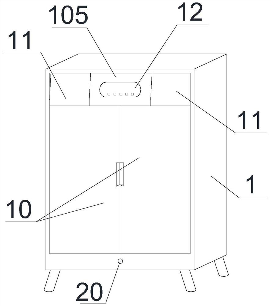
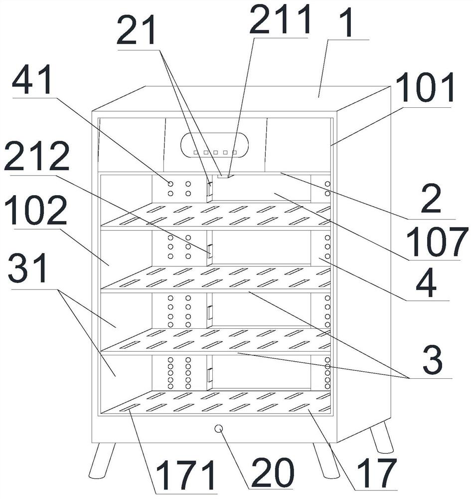
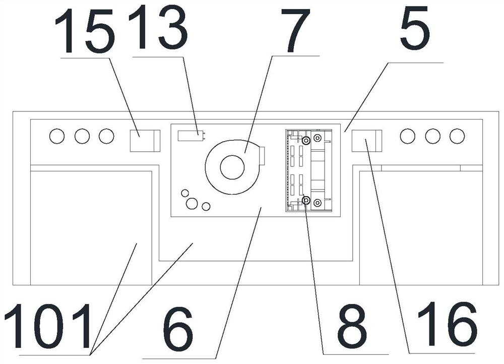
[0026] Example 1: Refer to the attached Figure 1-Figure 6 . A smart home disinfection and nursing shoe cabinet includes a shoe cabinet body 1. The inner cavity of the shoe cabinet body 1 is formed with an upper cavity 101 and a lower cavity 102 through a partition plate 2, and the lower cavity 102 passes through Each block partition 3 is divided into a plurality of shoe storage layers 31 which are distributed up and down. The partitions 3 can be fixed in the lower cavity 102 or on both sides of the lower cavity 102. Nails are respectively arranged on the inner wall of the shoe cabinet, and the partition 3 is placed on the nails; on both sides of the inner cavity in the shoe cabinet body 1 are arranged an air duct 4, and the upper end of the air duct 4 The head is located in the upper cavity 101, the lower end is located in the lower cavity 102, and the upper cavity 101 and the lower cavity 102 realize the mutual flow of airflow through the air duct 4. The one air duct 4 is us...

Embodiment 2

[0031] Example 2: On the basis of Example 1, refer to the attached Figure 7 with Figure 8 . Or the air duct 4 is formed by opening the upper end surfaces of the two side wall panels 108 in the shoe cabinet body 1 through the upper and lower end surfaces of the wall panel 108, and the inner wall surface of the wall panel 108 located in the upper cavity 101 has multiple openings. There are two vent holes, and multiple sets of through holes 41 are opened on the inner wall surface of the wall plate 108 in the lower cavity 102, and the upper and lower ports of the vent holes are respectively provided with partitions. When the air duct 4 is the wall plate 108 on both sides, the inner wall surface of the wall plate 108 is provided with multiple groups of movable wind deflectors 19 and the movable wind deflectors 19 are located at the corresponding through hole group 41; The wind plate 19 is composed of two guide rails 191 and a wind deflector 192. The two guide rails 191 are install...

Embodiment 3

[0032] Example 3: On the basis of Example 1 and Example 2. The bottom of the front of the shoe cabinet body 1 is provided with an infrared human body light sensor lamp 20. The infrared body light sensor lamp 20 includes a light emitting unit, a light sensor unit and an infrared sensor unit. The infrared body light sensor lamp 20 can be a An integrated piece composed of three devices. The signal input end of the control unit is connected to the signal output end of the light sensor unit and the signal output end of the infrared sensor unit through a data line, and the signal input end of the light-emitting unit is connected through a data line Connected to the signal output terminal of the control unit. When the ambient light is dark, the light sensor unit generates a corresponding sensing signal and the light sensor unit uploads the sensing signal to the control unit. At the same time, people pass through the infrared sensor unit, then the infrared sensor unit The corresponding...


PUM


Abstract

The invention relates to a smart home disinfection and nursing shoe cabinet capable of enabling shoes located on different layers to be consistent in drying effect and quality and automatically ventilating for dissipating heat after drying treatment, and a using method thereof. The two sides of an inner cavity in a shoe cabinet body are each provided with an air pipe, a plurality of through hole sets are formed in the front face of the air pipe body located in the lower cavity, and the number of through holes in the upper through hole set is smaller than that of through holes in the lower through hole set. An air duct for communicating the upper ports of the two air pipes is arranged in the upper cavity, a control circuit board is arranged in the air duct, a control unit is arranged in thecontrol circuit board, and an air blower and a heater are arranged in the air duct; and an exhaust hole is formed in the upper end face of the bottom plate, and an exhaust fan is arranged in the exhaust hole. The smart home disinfection and nursing shoe cabinet has the advantages that the drying effect and quality of shoes located on different layers can be consistent through the smart home disinfection and nursing shoe cabinet; and secondly, the smart home disinfection and nursing shoe cabinet can automatically ventilate and dissipate heat in time after the drying treatment.

Description

Technical field [0001] The invention relates to a smart home that can not only make the drying effect and quality of shoes on different layers consistent, but also automatically ventilate and dissipate heat after drying, and at the same time make the sterilization and disinfection effects and quality of different shoe layers consistent The disinfection and nursing shoe cabinet and its use method belong to the field of smart shoe cabinet manufacturing. Background technique [0002] CN 111109876 A. The name "a smart shoe cabinet", which includes a smart shoe cabinet body, the bottom of the smart shoe cabinet body is fixedly provided with a lower panel, and the top of the smart shoe cabinet body is fixedly provided with an upper panel, so A plurality of shoe cabinet cavities are opened on the front side of the smart shoe cabinet main body, and shoe cabinets are movably arranged in the plurality of shoe cabinet cavities, and a display screen is fixedly installed at the top of the fro...

Claims


Application Information

Patent Timeline
IPC IPC(8): A47B61/04A47B97/00A47L23/20A61L2/10A61L2/14A61L2/24B01D53/04F21V23/04F21V33/00F21Y115/10F21W131/301
CPCA47B61/04A47B97/00A47B2220/0077A47B2220/0091A47L23/205A61L2/10A61L2/14A61L2/24B01D53/04F21V23/0471F21V33/0012F21Y2115/10
Inventor 阮镇飚
Owner 浙江千百万智能设备有限公司
Learn More