Special component for posterior cervical single-door laminectomy

A technique of laminoplasty and single-door opening, which is applied in the fields of internal bone synthesis, medical science, and internal fixators, and can solve problems such as compression of the spinal cord, long length, and increased fatigue of surgeons.

Pending Publication Date: 2020-10-30
PEKING UNIV SHENZHEN HOSPITAL
View PDF1 Cites 0 Cited by
  • Summary
  • Abstract
  • Description
  • Claims
  • Application Information

AI Technical Summary

Problems solved by technology

[0004] Specifically, on the one hand, the lower splint and the abutment plate need to be set to a longer length so that they can be inserted into the incision end of the lamina and the abutment end of the side block. It is very difficult to operate, and it takes a lot of time to fit it into the incision end of the laminae and the abutting end of the side mass. This will make the operation time longer and increase the fatigue of the surgeon. On the other hand, for different The design of the angle between the lamina and the upper and lower splints is generally divided into narrow mouth and wide mouth. The narrow mouth is difficult in actual operation and takes more time, while the wide mouth is easy to install. However, even after the lamina is formed with titanium plates, Because of the long length of the wide-mouth lower splint, it will not fit well with the vertebral plate, so it may form iatrogenic spinal canal space-occupying stenosis, resulting in compression of the spinal cord

Method used


Image

  • Special component for posterior cervical single-door laminectomy
  • Special component for posterior cervical single-door laminectomy
  • Special component for posterior cervical single-door laminectomy

Examples


Embodiment Construction

[0044] The technical solution of the present invention will be described in detail below in conjunction with the accompanying drawings and specific embodiments, so as to understand the essence of the present invention more clearly and intuitively.

[0045] combine figure 1 , figure 2 , image 3 , Figure 4 , Figure 5 and Image 6 shown;

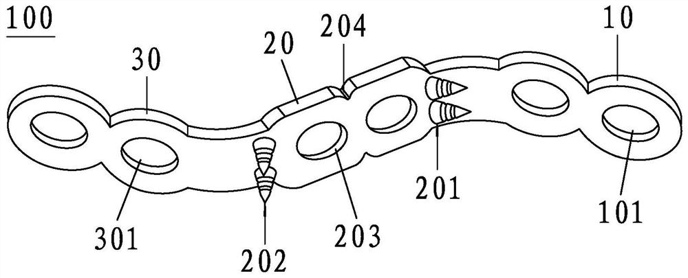
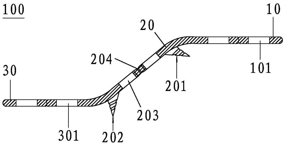
[0046] A special component 100 for posterior cervical single-door laminoplasty provided by the present invention includes a lamina fixation plate 10, a connecting compartment plate 20 and a side mass fixation plate 30;

[0047] The upper right end of the connecting warehouse plate 20 is connected with the lamina fixing plate 10, and the lower left end is connected with the side block fixing plate 30; the lamina fixing plate 10, the connecting warehouse plate 20 and the side block fixing plate 30 connected together to form a Z-shaped structure;

[0048] The lower bottom surface of the connecting warehouse plate 20 is close to its uppe...


PUM


Abstract

The invention discloses a special component for posterior cervical single-door laminectomy. The component comprises a vertebral plate fixing plate, a connecting bin plate and a side block fixing plate; the right upper end of the connecting bin plate is connected with the vertebral plate fixing plate, and the left lower end is connected with the side block fixing plate; a spine-shaped pricking block A is arranged on the lower bottom surface, close to the upper right end, of the connecting bin plate; a spine-shaped pricking block B is arranged on the lower bottom surface, close to the lower leftend, of the connecting bin plate; and the lower bottom surfaces of the vertebral plate fixing plate and the side block fixing plate, and the surfaces of the spine-shaped pricking block A and the spine-shaped pricking block B are rough surfaces and are provided with hydroxyapatite bone induction coatings. The spine-shaped pricking block A can be directly pricked into the outer edge of a vertebralplate cancellous bone section; the spine-shaped pricking block B is opened by an angle and a distance according to the actual lamina forming; the vertebral plate can be directly inserted into any bonesurface of a side block; immediate and stable fixation in an operation is provided, operation is convenient, safety and time saving are achieved, roughened bone induction coatings are adopted on thesurfaces of the bone contact surfaces of all components, osteoblasts can be attached to bones to grow into the vertebral plate, a permanent fixation forming vertebral plate is formed, and loosening and shifting of the forming vertebral plate can be effectively avoided.

Description

technical field [0001] The invention relates to the technical field of medical equipment, in particular to a special component for posterior cervical single-door laminoplasty. Background technique [0002] Clinically, for cervical spondylosis, cervical spinal canal stenosis, cervical ossification of ligaments and many other diseases with multi-segment compression of cervical spinal cord nerves, the most important and classic surgical method is cervical posterior single-door laminoplasty to expand the spinal canal decompression surgery. In the vast majority of cervical laminoplasty, laminoplasty titanium plates are required. Most of the commonly used titanium plates for laminoplasty do not have immediate stabilizing support and fixation. During the operation, the operation is completely controlled by the assistant. The operation safety is poor, and it is very easy to break the laminar axis and even iatrogenic spinal cord injury. At the same time, it lacks long-term and stab...

Claims


Application Information

Patent Timeline
Patent Type & Authority Applications(China)
IPC IPC(8): A61B17/70
CPCA61B17/7059A61B17/7074A61B2017/00831A61B2017/00867
Inventor 俞莉敏
Owner PEKING UNIV SHENZHEN HOSPITAL
Why Eureka
Try Eureka