
Centrifuge tube with double-layer structure

A double-layer structure, centrifuge tube technology, applied in the field of centrifuge tubes, to achieve the effect of eliminating biological safety hazards, preventing pollution, and reasonable design

Active Publication Date: 2020-10-30
SICHUAN CANCER HOSPITAL
View PDF30 Cites 1 Cited by
  • Summary
  • Abstract
  • Description
  • Claims
  • Application Information

AI Technical Summary

Problems solved by technology

[0006] The first aspect of the present invention is to solve the problem of safe and pollution-free separation and storage of the supernatant in the centrifuge tube, and provides a centrifuge tube with a double-layer structure, including an inner tube, the inner tube is provided with a first inner cavity and a first opening communicating with the first internal cavity,

Method used


Image

  • Centrifuge tube with double-layer structure
  • Centrifuge tube with double-layer structure
  • Centrifuge tube with double-layer structure

Examples


Embodiment 1

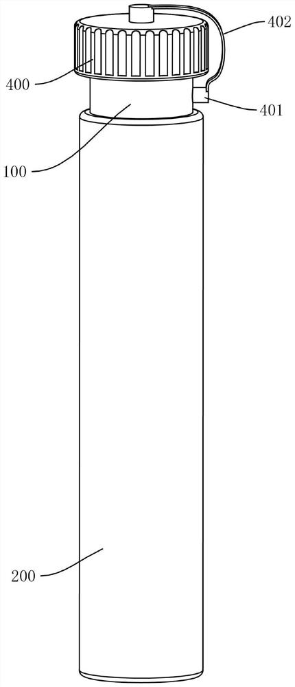
[0057] see Figure 1-Figure 14 , a double-layer centrifuge tube is provided in this embodiment, including an inner tube 100 and an outer tube 200, wherein the inner tube 100 is provided with a first internal cavity 101 and a first opening, and the first opening communicated with the first internal cavity 101,

[0058] The outer tube 200 is provided with a second internal cavity 201 and a second opening, the second opening communicates with the second internal cavity 201,

[0059] Such as figure 1 , Figure 8 , Figure 11 As shown, the outer tube 200 is sleeved on the outside of the inner tube 100, and an annular sealing ring 300 is arranged between the outer tube 200 and the inner tube 100, and the annular sealing ring 300 is fixed on the outer tube 200 for realizing sliding sealing. And form a closed cavity between the outer tube 200 and the inner tube 100, the inner tube 100 is provided with a communication hole 102 for communicating with the first inner cavity 101 and t...

Embodiment 2

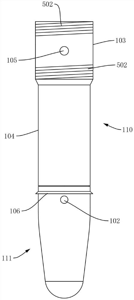
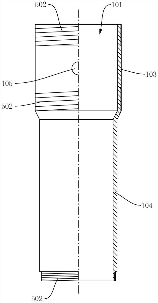
[0087] In order to facilitate the removal of the sediment at the lower part of the inner tube 100 after centrifugation, the main difference between this embodiment 2 and the above-mentioned embodiment 1 is that in the centrifuge tube provided by this embodiment, the inner tube 100 includes an upper tube section 110 (the upper pipe section 110 can be made of the first pipe section 103 and the second pipe section 104 described in embodiment 1) and the lower pipe section 111, the lower end of the upper pipe section 110 is integrally connected with the upper end of the lower pipe section 111 by screw thread , and the outer diameters of the upper pipe section 110 and the lower pipe section 111 are the same, such as Figure 2-Figure 4 shown;

[0088] The lower end of the lower pipe section 111 is closed, and the communicating hole 102 and the first restricting member 106 are respectively configured in the lower pipe section 111, such as Figure 4 as shown,

[0089] The first openi...


PUM


Abstract

The invention relates to a centrifuge tube with a double-layer structure. The centrifuge tube comprises an inner pipe and an outer pipe, the inner pipe is provided with a first internal cavity; the outer pipe is provided with a second inner cavity; the outer pipe is sleeved outside the inner pipe; an annular sealing ring is arranged between the outer pipe and the inner pipe, the annular sealing ring is fixed to the outer pipe and used for achieving sliding sealing, the inner pipe is provided with a communicating hole used for communicating the first inner cavity with the second inner cavity, the outer pipe is provided with a sealing piece used for sealing the communicating hole, and the outer pipe is used for moving from a first position to a second position relative to the inner pipe; theinvention provides the centrifugal tube with the double-layer structure, the supernatant can be conveniently and safely separated without pollution after the centrifugation is completed, and the supernatant can be effectively prevented from being dumped to disturb the sample gathered on the lower layer so as to pour out the precious and rare cell components along with the supernatant, and more importantly, the separated supernatant can be effectively stored and isolated so as to effectively prevent the biological pollution and effectively eliminate the biological safety hidden danger.

Description

technical field [0001] The invention relates to the technical field of medical devices, in particular to a centrifuge tube with a double-layer structure. Background technique [0002] Centrifuge tube is a kind of test tube used for centrifugation. It is mainly divided into three types: conical centrifuge tube, flat bottom centrifuge tube and round bottom centrifuge tube. Among them, conical centrifuge tube is the most used. In the medical field, centrifuge tube is usually used The separation and preparation of biological samples, that is, the biological sample suspension can be placed in a centrifuge tube and rotated at high speed under the drive of a rotating device. Due to the huge centrifugal force, the suspended tiny particles (such as cell organelles, biomacromolecules) Sedimentation, etc.) settle at a certain speed to achieve separation from the solution; for example, in the field of cytopathology, it is usually necessary to use centrifuge tubes to gather loose cells t...

Claims


Application Information

Patent Timeline
Patent Type & Authority Applications(China)
IPC IPC(8): B01L3/14
CPCB01L3/5021B01L2200/16
Inventor 贾世军
Owner SICHUAN CANCER HOSPITAL
Learn More