
Multi-station robot production line and production method

A technology of robots and production lines, applied in the direction of manufacturing tools, metal processing equipment, auxiliary devices, etc., can solve problems such as low production efficiency, and achieve the effect of saving manpower, improving processing efficiency, and improving utilization rate

Active Publication Date: 2020-10-30
NINGBO DAHONGYING UNIV
View PDF11 Cites 2 Cited by
  • Summary
  • Abstract
  • Description
  • Claims
  • Application Information

AI Technical Summary

Problems solved by technology

[0004] The purpose of the present invention is to solve the problem of how to better reduce the number of clamping times, simplify the clamping steps, and distribute the clamping order in the prior art due to the low production efficiency caused by the multiple re-clamping of the vehicle frame

Method used


Image

  • Multi-station robot production line and production method
  • Multi-station robot production line and production method
  • Multi-station robot production line and production method

Examples


Embodiment 1

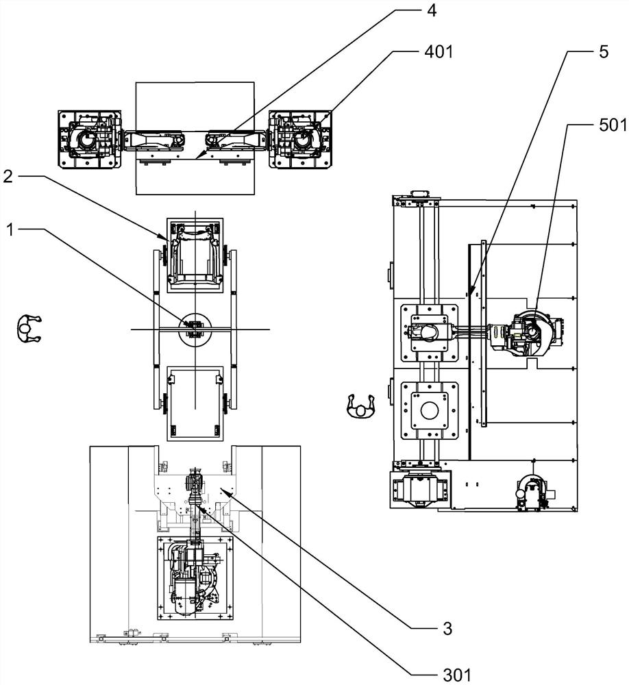
[0027] Such as figure 1 As shown, in a multi-station robot production line of the present invention, the spot welding worktable 3 is arranged on the front side of the rotary mechanism 1, the arc welding workbench 4 is arranged on the rear side of the rotary mechanism 1, and the repair welding workbench 5 is arranged on the rotary Right side of institution 1.

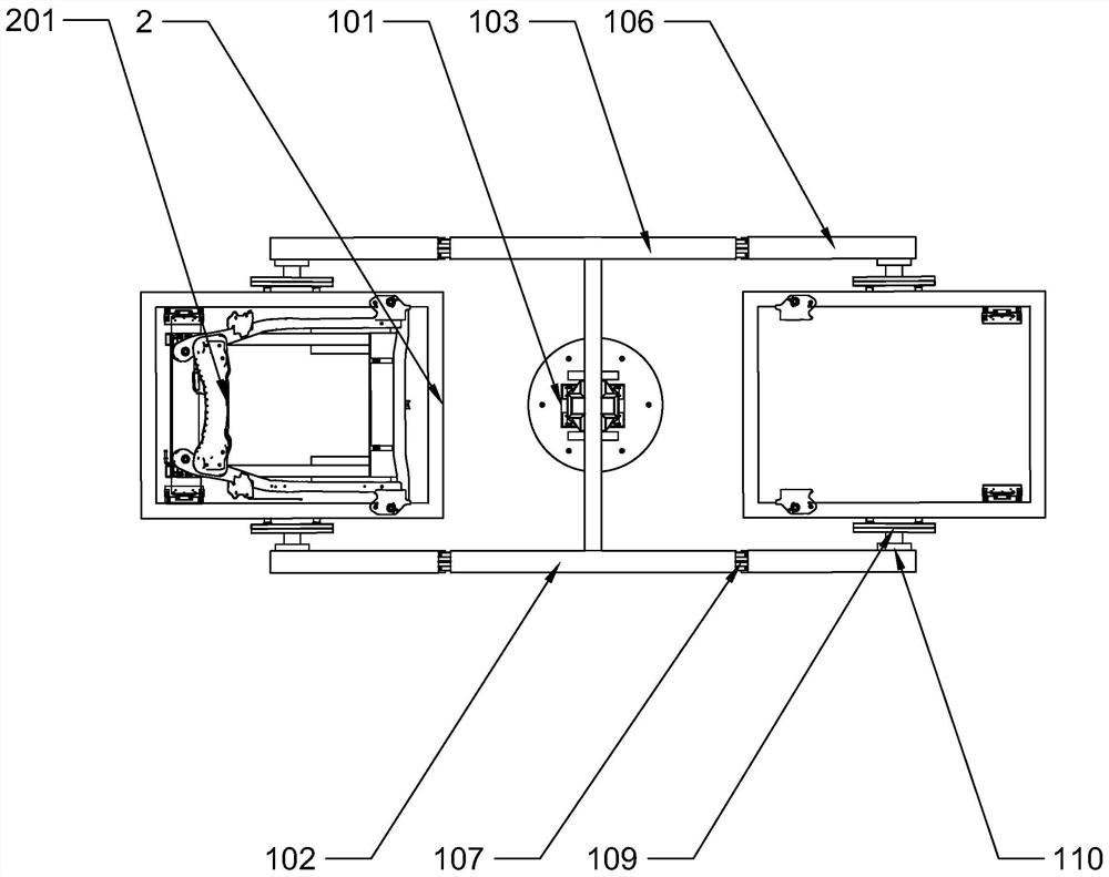
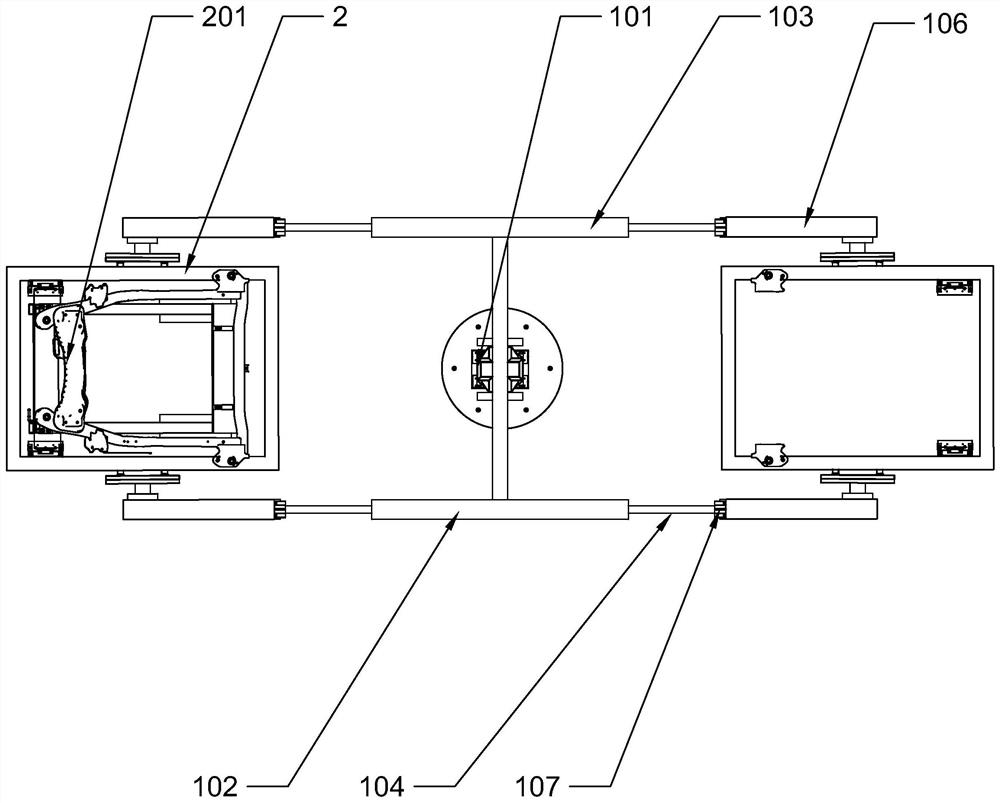
[0028] Such as figure 2 , image 3 and Figure 4 As shown, the slewing mechanism 1 includes a slewing base 101 and a support frame. The bottom of the revolving base 101 is provided with a motor, and the revolving base 101 is driven by the motor to realize horizontal rotation. The middle parts of the first support beam 102 and the second support beam 103 are fixedly connected to the swivel base 101, and the first support beam 102 and the second support beam 103 are symmetrical to the center of the swivel base 101, thereby forming an "H"-shaped support frame .

[0029]Lead screws 105 are vertically connected to midd...

Embodiment 2

[0036] The features of the multi-station robot production line in this embodiment are basically the same as those in Embodiment 1, except that the repair welding workbench is further provided with a main fixture seat 502 , an auxiliary fixture seat 503 and a slide table 504 .

[0037] Such as Figure 5 As shown, the slide table 504 is sequentially divided into a first area 505 , a second area 506 and a third area 507 (areas marked with dotted lines). The slide rail 509 and the ball screw pair 508 are arranged through the first area 505 , the second area 506 and the third area 507 , and the slide rail 509 and the ball screw pair 508 are parallel to each other. The secondary fixture seat 503 has the same structure as the main fixture seat 502 , both are slidably connected to the slide rail 509 , and both are driven by the ball screw pair 508 to slide on the slide rail 509 . Wherein the main clamp seat 502 slides in the first area 505 and the second area 506 , and the auxiliary ...


PUM

PropertyMeasurementUnit
lengthaaaaaaaaaa

Abstract

The invention discloses a multi-station robot production line, and aims to provide a multi-station robot production line which allows a frame to automatically move and turn in different welding stations. The multi-station robot production line of the technical scheme is characterized in that by arranging a rotating mechanism, the frame automatically moves among the different welding stations, by means of a turning device, the frame can turn, and by using a frame tool and the turning device in cooperation, not only is the problem that it is difficult to directly clamp the frame or to determinea turning center due to the irregular shape of the frame solved, but also the problem that deformation or strength reduction occurs near a welding spot due to residual welding heat when the frame moves among the different stations and needs to be clamped again is solved. The invention further provides a production method of the multi-station robot production line. Efficient machining of the frameis realized.

Description

technical field [0001] The invention relates to the technical field of automobile production, in particular to a multi-station robot production line and a production method of the multi-station robot production line. Background technique [0002] The frame is the core assembly that supports and connects the various parts of the car. It is generally formed by two longitudinal beams and several cross beams after spot welding and arc welding, and then repair welding of the connecting parts. Due to the large number of welding points on the frame and the complicated distribution positions, it is often necessary to transfer the frame multiple times and clamp it to different welding stations for welding. In the actual production process, clamping the frame to the welding fixture often accounts for 60%-75% of the total processing time, so how to reduce the number of clamping times, simplify the clamping steps, and distribute the clamping sequence is to shorten the total processing t...

Claims


Application Information

Patent Timeline
Patent Type & Authority Applications(China)
IPC IPC(8): B23K31/02B23K37/047
CPCB23K31/02B23K37/047
Inventor 俞国阳
Owner NINGBO DAHONGYING UNIV
Learn More