Magnet processing equipment and processing method

A technology of processing equipment and magnets, applied in metal processing equipment, other manufacturing equipment/tools, metal processing machinery parts, etc., can solve problems such as affecting slicing efficiency and inconvenient blank fixing

Inactive Publication Date: 2020-10-30
李明
View PDF0 Cites 1 Cited by
  • Summary
  • Abstract
  • Description
  • Claims
  • Application Information

AI Technical Summary

Problems solved by technology

After the magnet has completed the previous process of batching, smelting, stripping, powder making, and sintering, it is necessary to perform subsequent processes of punching, slicing, chamfering, electroplating, and magnetization on the blank produced by sintering. However, the existing slicing The equipment is not convenient to fix the blank, which affects the efficiency of slicing

Method used


Image

  • Magnet processing equipment and processing method
  • Magnet processing equipment and processing method
  • Magnet processing equipment and processing method

Examples


specific Embodiment approach 1

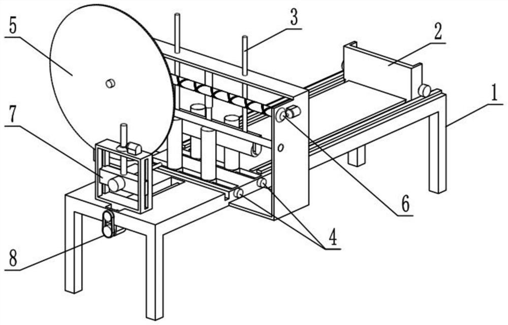
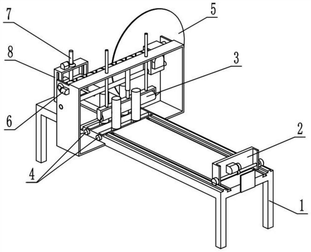
[0035] Such as Figure 1-10 As shown, a magnet processing equipment includes a support frame 1, a pushing mechanism 2, an upper clamping mechanism 3, a side end clamping mechanism 4, a cutting mechanism 5, a cutting moving mechanism 6, a drilling mechanism 7 and a drilling feeding mechanism 8. It is characterized in that: the push mechanism 2 is slidably connected to the rear end of the support frame 1, the upper clamping mechanism 3 is slidably connected to the upper end of the support frame 1, and the side clamping mechanism 4 is provided with Two, two side end clamping mechanisms 4 are all connected on the support frame 1, the two side end clamping mechanisms 4 are located at the front and rear ends of the top clamping mechanism 3, and the cutting moving mechanism 6 is connected to the support frame 1 The upper end of the upper end, the cutting mechanism 5 is fixedly connected to the cutting moving mechanism 6, the cutting mechanism 5 is located in front of the two side cla...

specific Embodiment approach 2

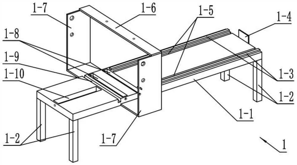
[0038] Such as Figure 1-10 As shown, the support frame 1 includes a support main board 1-1, a leg 1-2, a rack 1-3, a limit baffle 1-4, a push slideway 1-5, an upper horizontal plate 1-6, Side support plate 1-7, clamping slideway 1-8, cutter groove 1-9 and drilling slideway 1-10, supporting legs 1-2, rack 1-3 is provided with two, and the two racks 1-3 are fixedly connected to the support main board 1-1 in the front and rear direction, and the limit baffle 1-4 is fixedly connected to the rear end of the support main board 1-1, pushing the slideway 1-5 is provided with two, and the two pushing slideways 1-5 are arranged on the support main board 1-1 in the front and rear directions, and the clamping slideway 1-8 is provided with two, two clamping slideway 1-8 and The cutter grooves 1-9 are set on the support main board 1-1 in the left and right directions, the clamping slideway 1-8 at the rear end is located in front of the two pushing slideways 1-5, and the cutter groove 1-9 ...

specific Embodiment approach 3

[0040] Such as Figure 1-10 As shown, the push mechanism 2 includes a push plate 2-1, a push motor 2-2, a push side plate 2-3, a push shaft 2-4, a push gear 2-5 and a push slider 2-6, and the push plate The left and right ends of 2-1 are provided with push side plates 2-3, and the push shaft 2-4 is rotatably connected to the two push side plates 2-3, and both ends of the push shaft 2-4 are provided with push gears 2- 5. The push motor 2-2 is fixedly connected to the rear end face of the push plate 2-1, the push motor 2-2 is connected to the push shaft 2-4, and there are two push sliders 2-6, two push sliders 2- 6 are fixedly connected to the lower end of the push plate 2-1, and the two push sliders 2-6 are slidably connected in the two push slideways 1-5 respectively, and the two push gears 2-5 are connected to the two racks 1-5 respectively. 3 meshing transmission connection;

[0041] Start the push motor 2-2 to drive the push shaft 2-4 to rotate, and the push plate 2-1 is ...


PUM


Abstract

The invention relates to the field of magnet processing, in particular to magnet processing equipment and processing method. The method comprises the following steps that firstly, a magnet blank is placed on a supporting main board, so that the rear end of the magnet blank presses against a pushing plate; secondly, two sets of clamping rollers clamp both sides of the magnet blank in a blocking mode to the middle of the supporting main board, and an electric telescopic rod extends, so that an upper pressing roller presses against the upper end of the magnet blank; thirdly, the magnet blank is drilled through the arrangement that a lifting motor drives a drill bit to lift and lower down, and a feed motor drives the drill bit to move backwards; fourthly, a cutting moving motor drives a motormounting seat to drive a cutting blade to move back and forth; and fifthly, a pushing motor is started to drive the pushing plate to push the magnet blank to move forwards to complete reciprocating cutting of the magnet blank by the cutting blade.

Description

technical field [0001] The invention relates to the field of magnet processing, in particular to a magnet processing equipment and a processing method. Background technique [0002] The composition of the magnet is iron, cobalt, nickel and other atoms. The internal structure of the atom is relatively special, and it has a magnetic moment itself. A magnet can generate a magnetic field and has the property of attracting ferromagnetic substances such as iron, nickel, cobalt and other metals. After the magnet has completed the previous process of batching, smelting, stripping, powder making, and sintering, it is necessary to perform subsequent processes of punching, slicing, chamfering, electroplating, and magnetization on the blank produced by sintering. However, the existing slicing The equipment is not convenient to fix the blank, which affects the efficiency of slicing. Contents of the invention [0003] The purpose of the present invention is to provide a magnet process...

Claims


Application Information

Patent Timeline
Patent Type & Authority Applications(China)
IPC IPC(8): B23P23/02B23Q3/06
CPCB23P23/02B23Q3/06B23Q3/062
Inventor 李明
Owner 李明
Why Eureka
Try Eureka