Supercharge Your Innovation With Domain-Expert AI Agents!

A method for automatic separation of spindles for mule spinning

An automatic separation and spindle technology, applied in textiles and papermaking, etc., can solve problems such as inconvenient use, achieve the effects of reducing time-consuming processes, keeping clean, and improving processing efficiency

Active Publication Date: 2021-10-26
浙江沃伦特羊绒科技有限公司
View PDF10 Cites 0 Cited by
  • Summary
  • Abstract
  • Description
  • Claims
  • Application Information

AI Technical Summary

Problems solved by technology

[0004] The purpose of the present invention is to solve the problem that the yarn reel used by the mule spinning machine in the prior art needs to manually remove the spindle after the coating is completed, and then install the spindle in a new yarn reel. Inconvenient shortcomings, and a method for automatic separation of spindles for mule spinning

Method used


Image

  • A method for automatic separation of spindles for mule spinning
  • A method for automatic separation of spindles for mule spinning
  • A method for automatic separation of spindles for mule spinning

Examples


Embodiment 1

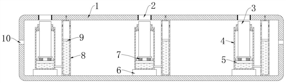
[0031] refer to Figure 1-5 , a method for automatic separation of spindles for mule spinning, the specific method of use is as follows:

[0032] S1. Conveying the spinning bobbin: place the spinning bobbin in the fixed box 14, open the drive mechanism, make the driving mechanism drive the conveyor belt to run, transfer the fixed box 14 to the top of the magnetic isolation box 1, and the circular groove and the ring Opening 2 is opposite;

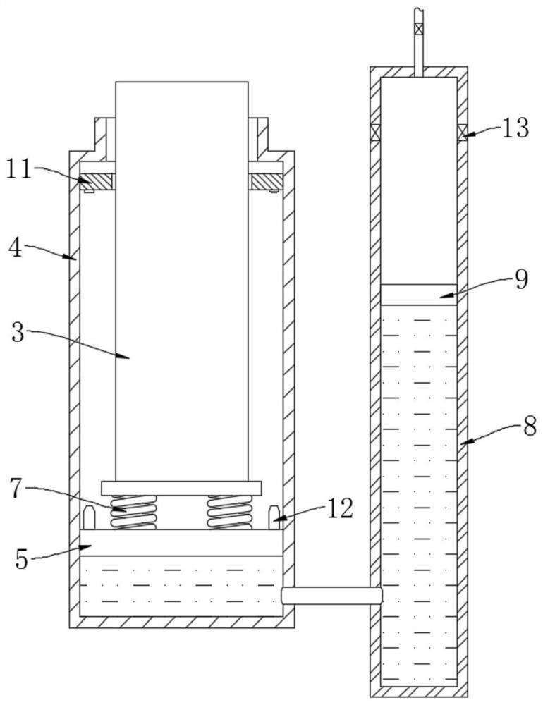
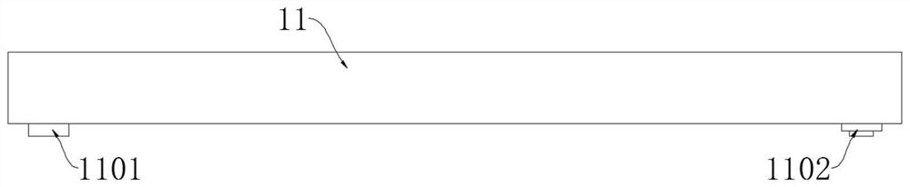
[0033] S2. Fixing the spinning bobbin: supplying power to the magnetic field generator 6 to excite the magnetic field. Under the repulsion of the magnetic field, the first sealing plate 5 moves upward until the two trigger keys 12 are connected to the first delay switch 1101 and the second delay switch 1101 respectively. The delay switch 1102 offsets, and the spinning bobbin is sleeved on the spindle 3 at this time;

[0034] S3, yarn covering: open the yarn covering mechanism 17, so that the yarn is covered on the outside of the spinning ...

Embodiment 2

[0050] refer to Figure 6 , the present embodiment differs from Embodiment 1 in that: each annular opening 2 is fixedly installed with a heightening baffle 18, the upper surface of the magnetic isolation box 1 is provided with a plurality of hollow redirection plates 19, and each sealing cylinder 8 The upper ends of each are connected to the corresponding hollow redirecting plate 19 through a straight pipe, and the plane where the top of the hollow redirecting plate 19 is located is located below the plane where the top of the heightening baffle 18 is located;

[0051] The hollow redirecting plate 19 is in the shape of a raised arc, and its side wall is provided with a plurality of air outlets in the circumferential direction. After the air flows from the sealed cylinder 8 to the hollow redirecting plate 19, it can only be discharged outward through the air outlets, thereby forming a radiant atmosphere. airflow.

[0052] When this embodiment is working, there will be thread e...


PUM


Abstract

The invention discloses a method for automatic separation of spindles for mule spinning, which mainly includes the following steps: S1, conveying the spinning bobbin; S2, fixing the spinning bobbin; S3, wrapping the yarn; S4, separating, during the separation process It also relates to a spindle self-separating device, including a driving mechanism, a transmission mechanism and a wrapping mechanism. The transmission mechanism includes a conveyor belt, and a plurality of fixed boxes are equidistantly installed on the conveyor belt through connecting pieces. The transmission mechanism One side of the mechanism is provided with a magnetic isolation box, and a plurality of annular openings are provided on the top wall of the magnetic isolation box, and a plurality of separation mechanisms are arranged in the magnetic isolation box, and each separation mechanism includes a straight cylinder, a magnetic field Generator and sealing cylinder, and each magnetic field generator is located directly below the corresponding straight cylinder. The invention has simple structure, low working energy consumption, and can realize the separation of the spindle and the yarn reel under the premise of the rotation of the spindle, which is convenient for the rapid replacement of the yarn reel and improves the processing efficiency.

Description

technical field [0001] The invention relates to the technical field of textile equipment, in particular to a method for automatically separating spindles for mule spinning. Background technique [0002] The mule spinning machine is a kind of textile equipment commonly used in the textile industry, because the worsted spinning process has less wool feel than the semi-worsted and woolen spinning processes, and the spun fabrics feel softer and more delicate, and have better pilling resistance. It is better, so it is loved by consumers. [0003] After the yarn reel used by the common mule spinning machine is covered, the spindle needs to be removed manually, and then the spindle is installed in a new yarn reel, which is inconvenient to use. The publication number is CN106757631B. The authorized patent relates to a spindle driving mechanism of a yarn covering machine. By setting up lifting platforms, limit blocks, conveyor belts and other devices, the automatic connection or sep...

Claims


Application Information

Patent Timeline
Patent Type & Authority Patents(China)
IPC IPC(8): D01H9/04
CPCD01H9/04
Inventor 黄石稳
Owner 浙江沃伦特羊绒科技有限公司
Features
  • R&D
  • Intellectual Property
  • Life Sciences
  • Materials
  • Tech Scout
  • Unparalleled Data Quality
  • Higher Quality Content
  • 60% Fewer Hallucinations
Learn More