
Handheld building material mounting device

A technology for installing devices and building materials, applied in the processing of building materials, construction, building components, etc., can solve problems such as increasing work difficulty, threatening life safety, and low efficiency, so as to reduce production safety hazards, strengthen structural stability, The effect of improving productivity

Active Publication Date: 2020-10-30
湖南中星建设集团有限公司
View PDF7 Cites 1 Cited by
  • Summary
  • Abstract
  • Description
  • Claims
  • Application Information

AI Technical Summary

Problems solved by technology

[0005] In order to overcome the prior art, the steel bar protective layer pads need to be placed between the vertical beams and the steel bars, and an anchoring force is applied to the vertical steel bars to strengthen the structural stability. It is stuck between the steel bar at a high place and the vertical beam, and then the iron wire is folded in half and inserted into the small hole of the steel bar protection block, and then the iron wire is wrapped around the steel bar to tie the steel bar protective layer to the steel bar. The installation is complicated and tedious, and the efficiency is high. Low, in addition, manual work at high altitude, it is difficult to clamp the steel bar protective layer pad between the steel bar and the vertical beam, after the card is inserted, the iron wire will be inserted into the small hole and tightened, which will increase the difficulty of the work, and a little improper operation Accident-prone and life-threatening shortcomings, the technical problem to be solved is: provide a hand-held building material installation device

Method used


Image

  • Handheld building material mounting device
  • Handheld building material mounting device
  • Handheld building material mounting device

Examples


Embodiment 1

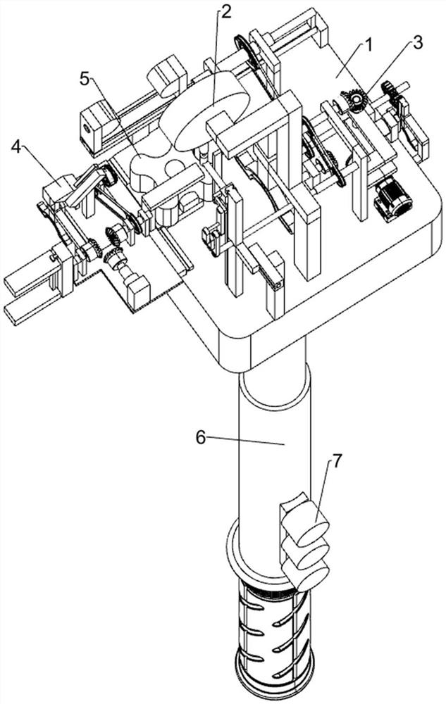
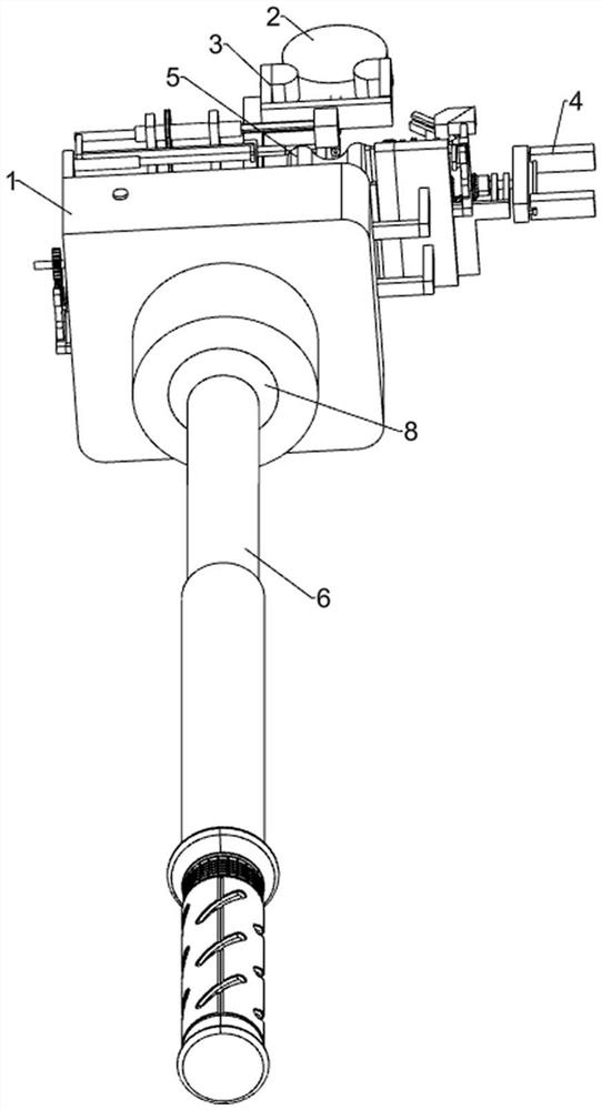
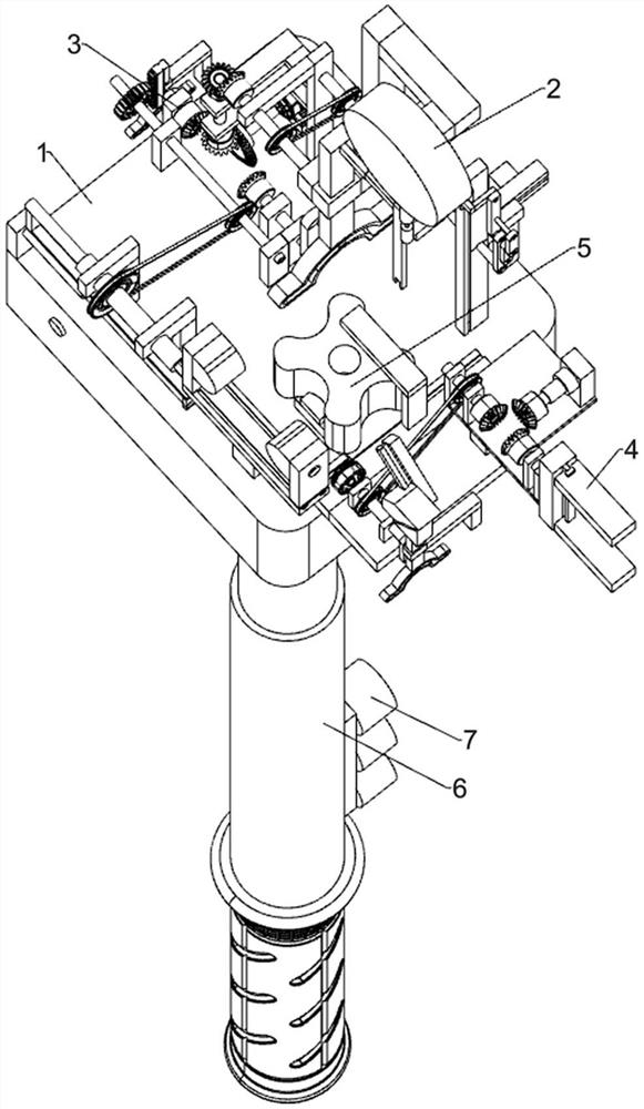
[0029] A hand-held building material installation device, such as Figure 1-8 As shown, it includes a first underframe 1, a double-layer wire threading mechanism 2, a steel pad rotation insertion mechanism 3, a wire tightening mechanism 4, a reinforced concrete pad 5, a first electric telescopic rod 6, a control switch 7 and an electric cardan shaft 8. A wire tightening mechanism 4, a reinforced cement pad 5, a double-layer wire threading mechanism 2 and a steel pad rotation insertion mechanism 3 are arranged above the first chassis 1 in sequence; the bottom of the first chassis 1 is connected with the electric universal shaft 8; One side of the double-layer wire-threading mechanism 2 is provided with a steel bar pad rotation insertion mechanism 3, and the other side of the double-layer wire-threading mechanism 2 is provided with a wire tightening mechanism 4; the double-layer wire-threading mechanism 2 is connected with the reinforced concrete pad 5; The electric cardan shaft...


PUM


Abstract

The invention relates to the field of building construction, in particular to a handheld building material mounting device. The technical problem to be solved is to provide the handheld building material installation device. The handheld building material installation device comprises a first underframe, a double-layer iron wire penetrating mechanism, a reinforcing steel bar pad rotary insertion mechanism, an iron wire tightening mechanism, a reinforced cement pad, a first electric telescopic rod and the like; the lower part of the first underframe is connected with an electric universal shaft; and the reinforcing steel bar pad rotary insertion mechanism is arranged at one side of the double-layer iron wire penetrating mechanism. According to the handheld building material mounting device,a steel wire is automatically folded and inserted into a small hole of the reinforced cement pad when in use, then the reinforced cement pad with the iron wire is automatically and rotatably clampedinto a vertical beam and a steel bar, the reinforced cement pad is automatically bound on the steel bar, and meanwhile, the reinforced cement pad can be smoothly installed from different angles by being held with the hands, so that the production efficiency is greatly improved, and the potential safety hazard of production is reduced.

Description

technical field [0001] The invention relates to the field of building construction, in particular to a hand-held building material installation device. Background technique [0002] Reinforcement protective layer pads are placed under the beams in the brick-concrete structure to expand the pressure-bearing area. Fire protection and other properties, the protective layer that bears the external force has anchoring force to the steel bar, and the anchoring force between the concrete and the steel bar is used, and the two are closely combined to participate in the work together. When the protective layer is too thin or missing, its anchoring force is reduced, thereby reducing the structure's ability to resist axial force and bending moment. [0003] In the prior art, a steel bar protective layer block is required between the vertical beam and the steel bar, and an anchoring force is applied to the vertical steel bar to strengthen the structural stability. During manual install...

Claims


Application Information

Patent Timeline
Patent Type & Authority Applications(China)
IPC IPC(8): E04G21/12E04C5/16E04C5/20
CPCE04G21/123E04C5/16E04C5/20
Inventor 周洪远
Owner 湖南中星建设集团有限公司
Learn More