
Wind-driven generator tower drum and tower footing yawing type wind-driven generator unit with same

A technology for wind turbines and wind turbines is applied in the control of wind turbines, wind turbines that are consistent with the wind direction, wind turbines and other directions, and can solve problems such as waste of tower manufacturing materials and reduced power generation performance of wind turbines.

Pending Publication Date: 2020-10-30
GUANGDONG MINGYANG WIND POWER IND GRP CO LTD
View PDF3 Cites 3 Cited by
  • Summary
  • Abstract
  • Description
  • Claims
  • Application Information

AI Technical Summary

Problems solved by technology

For tower-based yaw-type wind turbines, the yaw system is installed at the tower base. During the yaw process, the tower and the main engine of the wind turbine are relatively fixed and rotate together. At this time, the tower and its main external load (bending The direction of moment load) will also be relatively fixed. For example, if a tower with a traditional thin-walled ring structure is used, due to the inherent characteristics of the thin-walled ring tower structure, the design strength of the tower in all directions must be consistent with the maximum load direction of the tower. Therefore , virtually causing a waste of tower manufacturing materials
In addition, for downwind wind turbines, such as towers with a thin-walled ring structure, there is a significant tower shadow effect. When the wind turbine power and impeller diameter increase, the outer diameter of the tower increases accordingly. At this time, the tower shadow effect The more significant, it greatly reduces the power generation performance of the wind turbine

Method used


Image

  • Wind-driven generator tower drum and tower footing yawing type wind-driven generator unit with same
  • Wind-driven generator tower drum and tower footing yawing type wind-driven generator unit with same

Examples


Embodiment Construction

[0012] The present invention will be further described below in conjunction with specific examples.

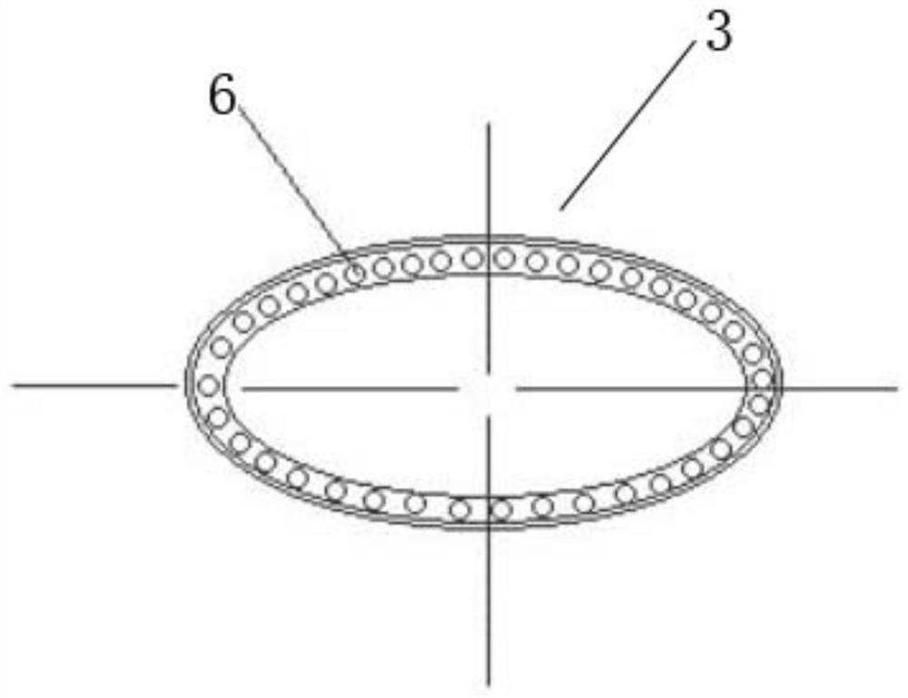
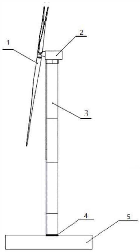
[0013] Such as figure 1 , figure 2 As shown, the wind power generator tower described in this embodiment and the tower-based yaw-type wind turbine with it, the tower-base yaw-type wind turbine includes an impeller system 1, a nacelle system 2, and a tower 3 , a yaw system 4, a foundation 5 and a connecting bolt 6, the impeller system 1 is installed on the nacelle system 2, the nacelle system 2 is fixedly installed on the top of the tower 3, and the bottom of the tower 3 passes through the yaw system 4 Transitionally installed on the foundation 5, the impeller system 1, the nacelle system 2 and the tower 3 can rotate around the central axis of the tower 3 as a whole when the unit yaws against the wind. At this time, the tower 3 bears the main external load (bending The direction of the moment load) is relatively fixed relative to the nacelle 2, so the cross-section of the to...


PUM


Abstract

The invention discloses a wind-driven generator tower drum and a tower footing yawing type wind-driven generator unit with the same. The cross section of the tower drum is of an oval structure; the wind-driven generator unit is fixedly installed at the top of the tower drum; the length axis of the oval section of the tower drum is maintained parallel with the main axis of the unit when the inclination angle of a main machine of the unit is 0 degree; a yawing system of the unit is installed at the tower footing position of the tower drum; and in the process of yawing wind aligning of the unit,a cabin system of the unit, an impeller, the tower drum and tower drum connecting bolts can rotate as a whole around the central axis of the tower drum. Through the arrangement of the tower drum whichis of an oval structure, under the condition that no change is made to preparation materials of the tower drum and the bending resistance section coefficient and tower drum load bearing requirementsare met, the weight and cost of the tower drum can be effectively lowered, the economic benefit is good, the tower drum is particularly applicable to downwind direction wind-driven generator units, the tower shadow effect of the units can be effectively improved, and the generation performance of the units can be improved.

Description

technical field [0001] The invention relates to the technical field of towers and wind power generators, in particular to a wind power generator tower and a tower base yaw type wind power generator with the same. Background technique [0002] In the prior art, the yaw system of the wind power generating set is usually designed on the top of the tower, and the wind turbine tower is connected to the foundation in a completely fixed manner. Due to the instability of the wind direction in the actual operation of the wind turbine, its yaw system must be adjusted in real time according to the change of the wind direction. Therefore, the tower of the wind turbine needs to bear external loads from different directions during the whole life cycle. For this reason, the towers of traditional wind turbines mostly adopt thin-walled ring structures, so as to ensure that the towers have high bearing capacity and design strength for loads from all directions. For tower-based yaw-type wind ...

Claims


Application Information

Patent Timeline
Patent Type & Authority Applications(China)
IPC IPC(8): F03D13/20F03D1/00F03D7/04
CPCF03D13/20F03D1/00F03D7/0204Y02E10/72Y02E10/728
Inventor 夏宗朝邹荔兵张启应高文飞周名军霍仕环段博志孙加鹏李学旺刘凡鹰赵春雨
Owner GUANGDONG MINGYANG WIND POWER IND GRP CO LTD
Learn More