
Adjustable heat transfer heat exchanger

A heat exchanger, adjustable technology, applied in the direction of indirect heat exchanger, heat exchanger type, heat exchanger shell, etc., can solve the problems of regulation, tube wall deposition dirt, reduce heat exchange efficiency of heat exchanger, etc.

Active Publication Date: 2020-10-30
ZHENGZHOU UNIVERSITY OF AERONAUTICS
View PDF7 Cites 2 Cited by
  • Summary
  • Abstract
  • Description
  • Claims
  • Application Information

AI Technical Summary

Problems solved by technology

A heat exchanger is a device used to transfer heat from a hot fluid to a cold fluid to meet the specified process requirements. It is an industrial application of convective heat transfer and heat conduction. The shell and tube heat exchanger is currently the most widely used heat exchanger. Thermal equipment, which is characterized by firm structure, high reliability, and wide adaptability. The shell-and-tube heat exchanger is composed of a shell and a tube bundle containing many tubes. The cold and hot fluids exchange heat through the tube wall. For heat exchangers, the exchange time required for fluids with different specific heat capacities is also different. The exchange efficiency of existing heat exchangers is fixed and cannot be adjusted according to the specific heat capacity of the fluid. In this case, dirt is easily deposited on the tube wall, which reduces the heat transfer efficiency of the heat exchanger

Method used


Image

  • Adjustable heat transfer heat exchanger
  • Adjustable heat transfer heat exchanger
  • Adjustable heat transfer heat exchanger

Examples


Embodiment Construction

[0019] The preferred embodiments of the present invention will be described below in conjunction with the accompanying drawings. It should be understood that the preferred embodiments described here are only used to illustrate and explain the present invention, and are not intended to limit the present invention.

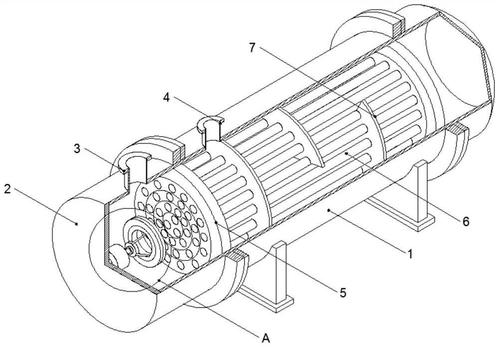
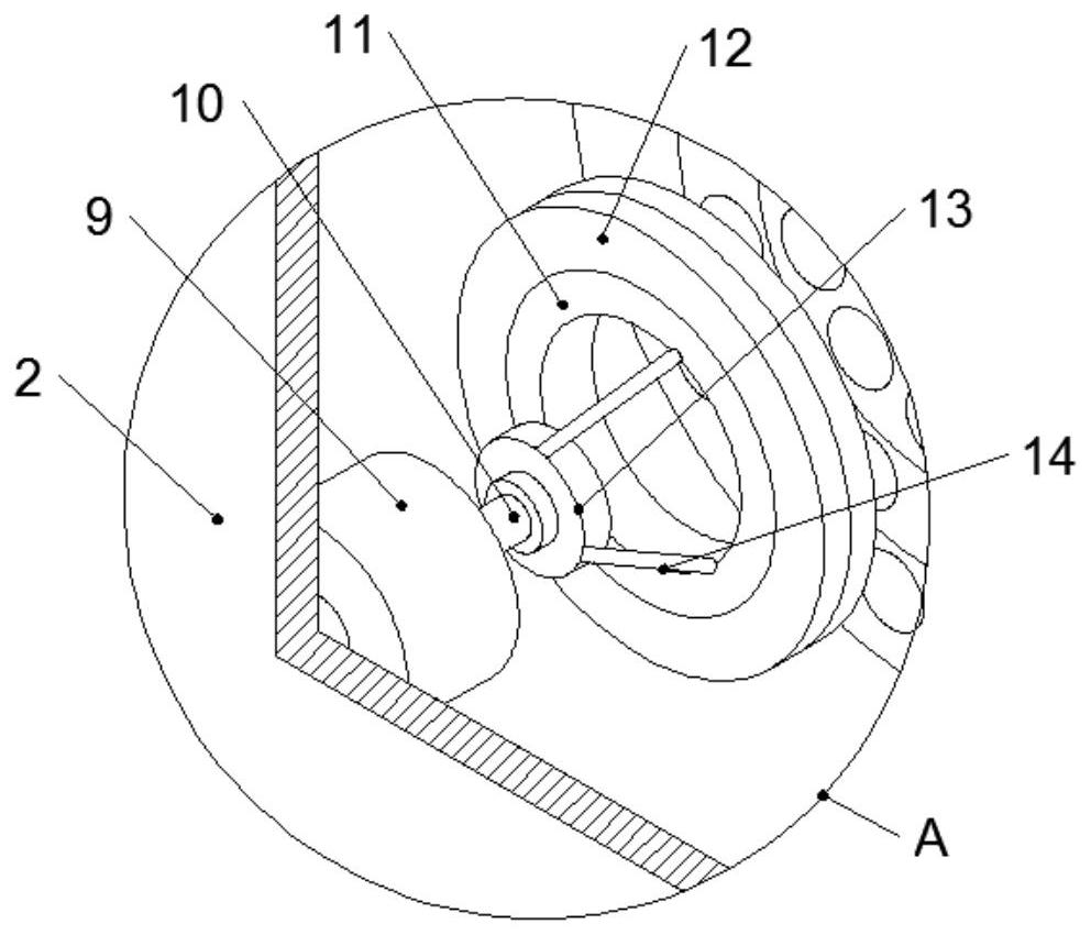
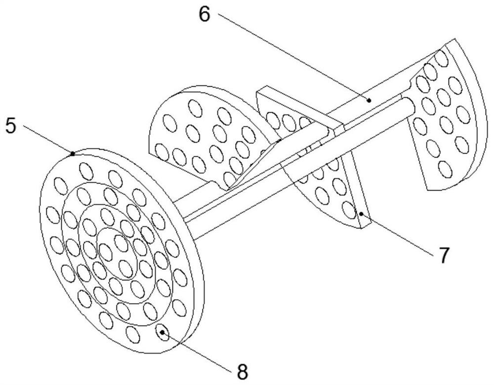
[0020] Example: such as Figure 1-4 As shown, an adjustable heat transfer heat exchanger of the present invention includes a main shell 1, the main shell 1 is cylindrical, and seal heads 2 are installed on both ends respectively, and the head at one end The top of 2 is fixed with a cold fluid inlet 3, and the bottom of one end head 2 is provided with a cold fluid outlet. The inside of the main shell 1 is sealed with a tube plate 5 near the connection of the head 2, and the tube Several groups of heat transfer tubes 6 are connected between the plates 5, and the main casing 1 is fixedly installed with multiple groups of baffles 7 on the outside close to the heat trans...


PUM


Abstract

The invention discloses an adjustable heat transfer heat exchanger. The adjustable heat transfer heat exchanger comprises a main shell which is cylindrical, end sockets are mounted at the two ends ofthe main shell in a sealed mode correspondingly, a cold fluid inlet is fixedly formed in the top end of the end socket at one end, a cold fluid outlet is formed in the bottom of the end socket at theother end, pipe plates are mounted at the positions, close to the end sockets, of the interior of the main shell in a sealed mode, a plurality of heat transfer pipes are connected between the pipe plates, a plurality of baffle plates are fixedly mounted on the outer side, close to the heat transfer pipes, of the main shell, a plurality of mounting holes used for mounting the heat transfer pipes are formed in the baffle plates, phonon rings are fixedly embedded in the mounting holes, and inner rings of the phonon rings are in sealed connection with the outer walls of the heat transfer pipes. According to the adjustable heat transfer heat exchanger, the inner walls of the heat transfer pipes and the outer walls of the baffle plates are rapidly descaled and prevented from being scaled throughthe phonon rings inside the baffle plates, and the problems that dirt is extremely likely to be deposited on the pipe walls, and the heat exchange efficiency of the heat exchanger is reduced are effectively solved.

Description

technical field [0001] The invention relates to the technical field of heat exchangers, in particular to an adjustable heat transfer heat exchanger. Background technique [0002] With the acceleration of my country's industrialization and urbanization process, and the economic growth of developing countries around the world, the demand for heat exchangers in the domestic market and export market will continue to grow. Heat exchanger is a kind of general equipment widely used in chemical industry, oil refining, power, food, light industry, atomic energy, pharmaceutical, machinery and many other industrial sectors. It plays an important role in production. In chemical production, heat exchanger can be used as heating coolers, condensers, evaporators and reboilers etc. A heat exchanger is a device used to transfer heat from a hot fluid to a cold fluid to meet the specified process requirements. It is an industrial application of convective heat transfer and heat conduction. Th...

Claims


Application Information

Patent Timeline
IPC IPC(8): F28D7/16F28F9/02F28F9/24F28F27/00F28G7/00
CPCF28D7/16F28F9/0231F28F9/24F28F27/00F28G7/00Y02P20/10
Inventor 张丽娜
Owner ZHENGZHOU UNIVERSITY OF AERONAUTICS
Learn More