Method for correcting error of quasi-optical cavity dielectric constant test along with frequency change

A frequency change, dielectric constant technology, applied in the field of detection, can solve the problem of quasi-optical cavity dielectric constant test error and other problems

Pending Publication Date: 2020-10-30
CHINA ELECTRONIS TECH INSTR CO LTD
View PDF3 Cites 3 Cited by
  • Summary
  • Abstract
  • Description
  • Claims
  • Application Information

AI Technical Summary

Problems solved by technology

[0005] In view of the deficiencies in the prior art, the purpose of the present invention is to provide a method for correcting the error of quasi-optical cavit

Method used


Image

  • Method for correcting error of quasi-optical cavity dielectric constant test along with frequency change
  • Method for correcting error of quasi-optical cavity dielectric constant test along with frequency change
  • Method for correcting error of quasi-optical cavity dielectric constant test along with frequency change

Examples


Embodiment

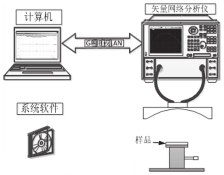
[0030] In a typical implementation of the present invention, this embodiment provides a method for correcting the error of quasi-optical cavity dielectric constant test as the frequency changes. For error correction, the quasi-optical cavity field theory derived from the multiple point source theory is used for analysis, and the error amplitude is corrected considering the influence of the longitudinal field component. The phase error correction is carried out through the corresponding relationship between the frequency change phenomenon of the dielectric test results and the theory.

[0031] Specifically, the following steps are included:

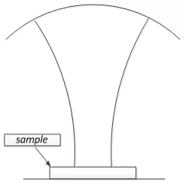
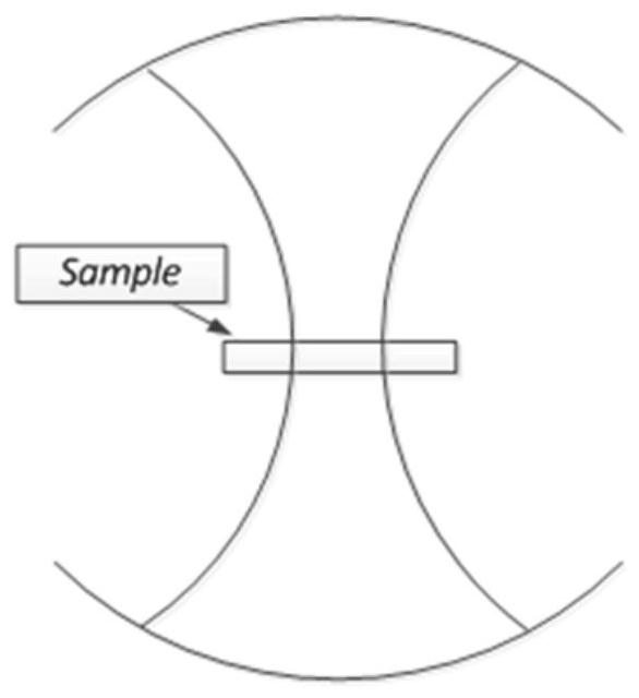
[0032] 1) Analyze the phase distribution of the Gaussian beam in the quasi-optical cavity;

[0033] 2) According to the matching relationship of the electromagnetic field boundary conditions at the upper surface of the sample to be tested, that is, the interface between the air and the medium region, the actual phase distribution and the e...


PUM


Abstract

The invention discloses a method for correcting an error of a quasi-optical cavity dielectric constant test along with frequency change, belongs to the field of detection, and can solve the problem ofthe error of the quasi-optical cavity dielectric constant test along with the frequency change. The method comprises the following steps of: analyzing Gaussian beam phase distribution in a quasi-optical cavity; obtaining actual phase distribution and an electric field and magnetic field expression of the upper surface of a sample according to the boundary condition relationship of the upper surface of the to-be-detected sample, namely an electromagnetic field at an interface of air and a medium region; considering the longitudinal field component of the electric field in the quasi-optical cavity, and listing the transverse field component and the longitudinal field component of the electric field in the quasi-optical cavity into a calculation step; and substituting the transverse field component and the longitudinal field component into a formula for calculation.

Description

technical field [0001] The invention belongs to the field of detection, and in particular relates to a method for correcting errors in quasi-optical cavity dielectric constant testing with frequency variation. Background technique [0002] The statements herein merely provide background information related to the present invention and do not necessarily constitute prior art. [0003] For the testing of dielectric properties of materials, the commonly used testing methods mainly include plate capacitance method, network parameter method, resonance method, free space method and quasi-optical cavity method. Among them, the quasi-cavity method has the advantages of simple operation, good mode purification effect, and strong test adaptability. The quasi-cavity method has two structures: a semi-symmetrical quasi-cavity (flat-concave cavity) and a symmetrical quasi-cavity (double-spherical cavity). The schematic diagram of the structure is shown in Figure 1. Among them, the flat ...

Claims


Application Information

Patent Timeline
IPC IPC(8): G01R27/26
CPCG01R27/2682
Inventor 邹翘赵锐王亚海江子奇年夫顺
Owner CHINA ELECTRONIS TECH INSTR CO LTD
Why Eureka
Try Eureka