
Beam unit simulated wind power blade static test method, device and equipment

A wind power blade and testing method technology, applied in the field of computer communication, can solve problems such as high requirements for basic knowledge and software operation skills, high difficulty in use, large deformation of blade testing, etc., achieving low requirements for computing resources, reducing operation difficulty, The effect of reducing computational cost

Active Publication Date: 2020-10-30
JILIN CHONGTONG CHENGFEI NEW MATERIAL
View PDF3 Cites 2 Cited by
  • Summary
  • Abstract
  • Description
  • Claims
  • Application Information

AI Technical Summary

Problems solved by technology

This method is difficult to use, the calculation iteration time is long, and the load of the blade section cannot be obtained intuitively
[0003] Wind turbine blades need to be statically tested. The existing methods have the following problems: 1. It must be equipped with commercial finite element analysis software (such as: ANSYS, ABQUS, MSC.Nastran, etc.), and the purchase of these software is often expensive; 2. It cannot Real-time knowledge of the bending moment borne by each section of the blade under the current iteration step makes iterative calculation difficult; 3. The software requires a high level of basic knowledge and software operation skills of the user; 4. There is large deformation in the blade test, and the loading force It is difficult to follow the changes

Method used


Image

  • Beam unit simulated wind power blade static test method, device and equipment
  • Beam unit simulated wind power blade static test method, device and equipment
  • Beam unit simulated wind power blade static test method, device and equipment

Examples


Embodiment Construction

[0020] In order to make the purpose, technical solution and advantages of the present invention clearer, the present invention will be further described in detail below through specific implementation methods in conjunction with the accompanying drawings. It should be understood that the specific embodiments described here are only used to explain the present invention, not to limit the present invention.

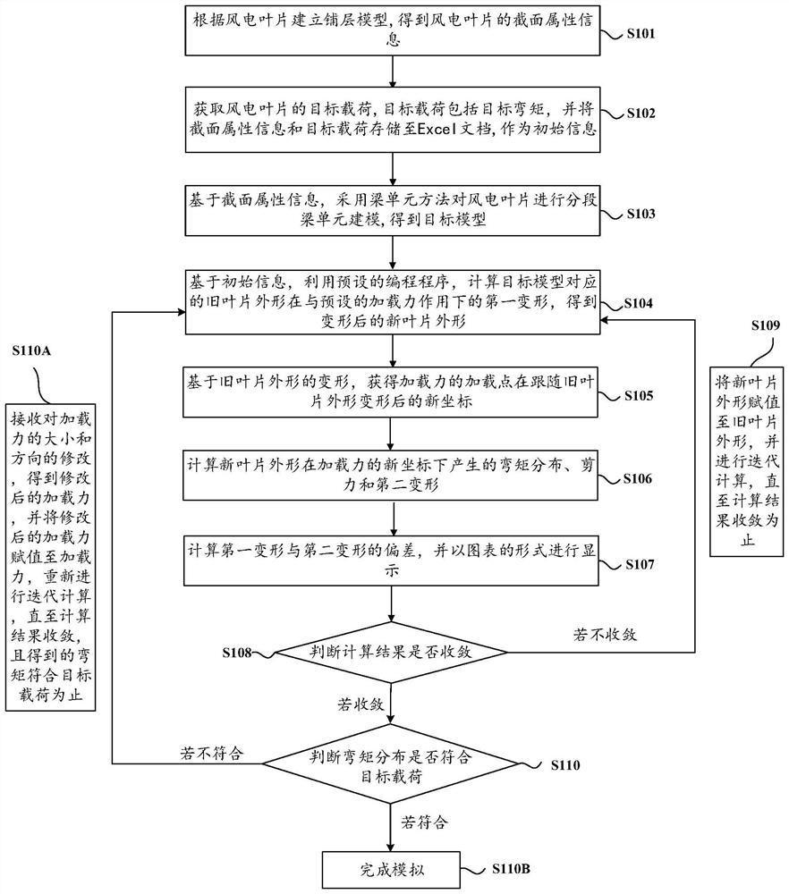
[0021] In one embodiment, such as figure 1 As shown, a static test method for wind turbine blades simulated by beam elements is provided, including the following steps:

[0022] S101 establishes a layup model according to the wind power blade, and obtains cross-sectional attribute information of the wind power blade.

[0023] Specifically, the ply model of the target wind power blade is established according to the wind power blade. FOCUS software can be used here, and then according to the ply model, the section property information of the wind power blade can be obtained...


PUM


Abstract

The invention provides a beam element simulated wind power blade static test method, device and equipment. The method comprises the steps: carrying out the layering modeling on a wind power blade to obtain section attribute information, and storing the section attribute information and target load information required to be verified by design in an Excel document to serve as initial information for standby application; carrying out the modeling on the wind power blade in a beam element modeling mode, and calculating the bending moment and deformation of the wind power blade under the action ofloading force; and then, according to software prompts, adjusting the magnitude and direction of the loading force until deformation convergence and bending moment meet target load verification requirements, and completing the simulation of the static test scheme of the wind turbine blade. According to the scheme, the operation is easy, the ratio of the load of each iteration to the target load and the change of blade deformation along with the loading force can be displayed in real time, and simulation intuition is provided; the convergence speed of the calculation result is high, the calculation speed is increased, a self-made programming program is adopted as a whole to replace previous finite element analysis software, and the cost is reduced.

Description

technical field [0001] The invention relates to the technical field of computer communication, in particular to a method, device and equipment for static testing of wind power blades simulated by beam units. Background technique [0002] The finite element method is mostly used in the static test scheme simulation of wind turbine blades today. In this method, the blade layer simulation is carried out first, and then the finite element model is established, and the finite element model is loaded iteratively. This method is difficult to use, the calculation iteration time is long, and the load of the blade section cannot be obtained intuitively. [0003] Wind turbine blades need to be statically tested. The existing methods have the following problems: 1. It must be equipped with commercial finite element analysis software (such as: ANSYS, ABQUS, MSC.Nastran, etc.), and the purchase of these software is often expensive; 2. It cannot Real-time knowledge of the bending moment ...

Claims


Application Information

Patent Timeline
Patent Type & Authority Applications(China)
IPC IPC(8): G06F30/20G06F30/17G06F119/14
CPCG06F30/20G06F30/17G06F2119/14
Inventor 许蕾张石强罗莎莎袁亚丽托马斯唐雪
Owner JILIN CHONGTONG CHENGFEI NEW MATERIAL
Learn More