Camera calibration method for optical surface shape measurement and device for realizing method

A camera calibration and optical surface technology, applied in the field of precision engineering, can solve problems such as deviation of light position and direction, influence of measurement accuracy, etc., to achieve the effect of improving calibration accuracy

Pending Publication Date: 2020-10-30
FUDAN UNIV
View PDF0 Cites 2 Cited by
  • Summary
  • Abstract
  • Description
  • Claims
  • Application Information

AI Technical Summary

Problems solved by technology

There will be deviations in the position and direction of the obtained light, which will affect the measurement accuracy

Method used


Image

  • Camera calibration method for optical surface shape measurement and device for realizing method
  • Camera calibration method for optical surface shape measurement and device for realizing method
  • Camera calibration method for optical surface shape measurement and device for realizing method

Examples


Embodiment Construction

[0016] The present invention will now be described in further detail in conjunction with the accompanying drawings and embodiments.

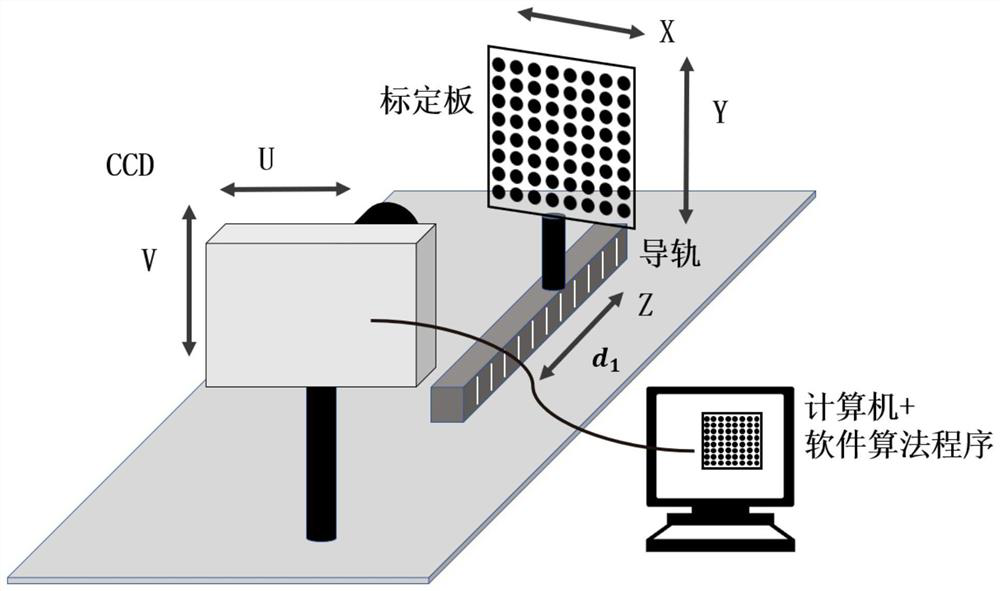
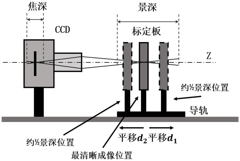
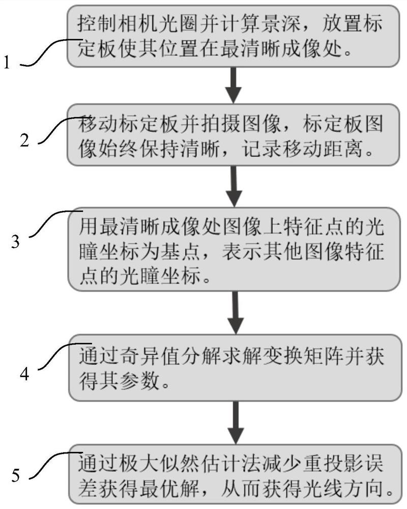
[0017] Such as figure 1 , figure 2 Shown is the schematic diagram of the structure of the calibration device of the present invention, from which it can be seen that the optical path of the experimental equipment, the camera is a small pupil camera, and the image is taken after moving the calibration plate in parallel, see Figure 4 ; image 3 It is a flowchart of the calibration process of the present invention, including the following steps:

[0018] Step 1. Control the camera aperture and calculate the depth of field, and place the calibration plate so that it is at the clearest image;

[0019] Step 2, move the calibration plate and take images, the image of the calibration plate is always clear, record the moving distance;

[0020] Step 3, use the pupil coordinates of the feature points on the image at the clearest imaging point as the...


PUM


Abstract

The invention relates to the technical field of precision engineering, in particular to a camera calibration method in vision measurement and deflection. A camera calibration method for optical surface shape measurement is characterized in that a camera is arranged on a guide rail, a calibration plate containing round spot characteristics can move along the guide rail, and the method comprises thefollowing steps: respectively shooting corresponding position images at a focusing position and a plurality of front-back symmetrical positions; taking pupil coordinates of the feature points on theimage at the focusing position as base points, and performing linear interpolation through a triangular mesh method to represent pupil coordinates of other image feature points; constructing a corresponding equation between a pixel point and an actual object coordinate through affine transformation and a distortion item, and solving an object image transformation matrix parameter through singularvalue decomposition; and reducing reprojection errors through a maximum likelihood estimation method to obtain an optimal solution, and obtaining the light direction. Compared with an existing cameracalibration technology, the method has the advantages of being high in precision, wide in applicability, convenient to operate and the like.

Description

technical field [0001] The invention relates to the technical field of precision engineering, and mainly relates to a small-pupil camera calibration device and method in visual measurement and deflection surgery. Background technique [0002] In modern precision measurement, deflection measurement method is a high-precision measurement technology of optical surface shape based on fringe reflection. Its main principle is to project regular fringes to the surface to be measured, and the fringes are deformed after being reflected by the surface to be measured, and the deformed pattern is captured by a CCD camera, and the geometric relationship between the object image point and the surface point to be measured is obtained by using the triangulation method. Back-to-school of incident light and reflected light, deduce the gradient distribution of the surface to be measured according to the angle bisector, and obtain the surface shape height distribution by integral [Xu Xueyang. O...

Claims


Application Information

Patent Timeline
Patent Type & Authority Applications(China)
IPC IPC(8): G06T7/80G06T3/00G06T3/40G06F17/11
CPCG06F17/11G06T3/0006G06T3/4023G06T7/80
Inventor 张祥朝
Owner FUDAN UNIV
Why Eureka
Try Eureka