A self-radiating rare earth permanent magnet synchronous motor

A rare earth permanent magnet, synchronous motor technology, applied in the direction of electromechanical devices, electrical components, electric components, etc., can solve the problems of reduced heat sink effect, inconvenient disassembly and installation, limited gap between the machine compartment and front and rear covers, etc., to improve self-heating effect, improve self-heat dissipation capacity, improve the effect of heat dissipation effect

Active Publication Date: 2021-07-27
湖南普东科技有限责任公司
View PDF0 Cites 0 Cited by
  • Summary
  • Abstract
  • Description
  • Claims
  • Application Information

AI Technical Summary

Problems solved by technology

[0003] During the use of the current rare earth permanent magnet synchronous motor, most of the outside air enters the motor through the gap between the machine compartment and the front and rear covers to cool down the inside of the motor, but the gap between the machine compartment and the front and rear covers is limited. , and currently only a set of fans are installed on the motor shaft inside the synchronous motor, it is impossible to improve the self-heating effect of the rare earth permanent magnet synchronous motor; However, most of the traditional heat sinks are directly welded on the outside of the machine compartment. At this time, the effect of the heat sink will be greatly reduced, so that the heat dissipation effect of the synchronous motor cannot be further improved; while the current rare earth permanent magnet synchronous motor is for It is convenient for air to flow inside the motor, and there are gaps and through holes on purpose. Although it is convenient for air flow, when the motor is not in use, the dust in the external environment will slowly enter the interior of the machine compartment with the air flow and cover it. On the internal components of the motor, it affects the actual effect of the subsequent use of the motor; at the same time, the front cover and the rear cover of the current rare earth permanent magnet synchronous motor are fixedly connected to the machine compartment through multiple sets of fixing screws, which is very difficult to disassemble and install. It is inconvenient, and it is impossible to further improve the stability of the connection between the front and rear machine covers and the machine compartment

Method used


Image

  • A self-radiating rare earth permanent magnet synchronous motor
  • A self-radiating rare earth permanent magnet synchronous motor
  • A self-radiating rare earth permanent magnet synchronous motor

Examples


Embodiment 1

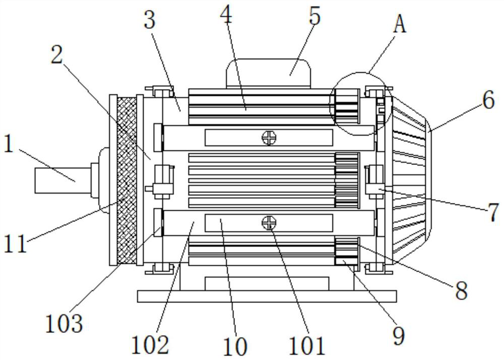
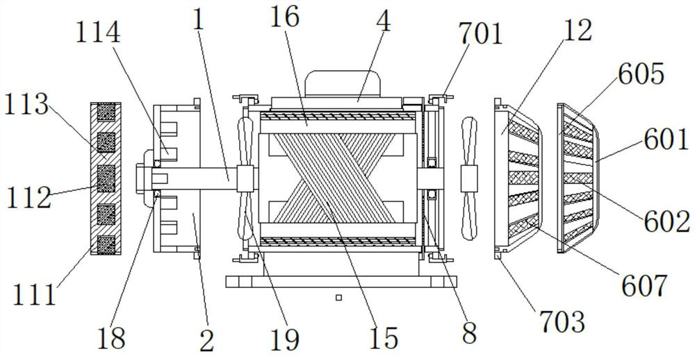
[0034] Example 1, such as Figure 1-3 As shown, when the external air sucks the chassis 3, it is necessary to turn the inner thread ring 113 such that the pass groove A111 and the pass groove B114 can be coincident, thereby enabling the outside air through the filter B112 filtered, after passing After passing through the groove A111 and the pass groove B114, it enters the interior of the chamber 3, and then rotates the outer cover 601 such that the outer cover 601 and the strip through hole 602 on the rear cover 12 are coincident with each other, and the air inside the cabinet 3 is from the strip The shaped hole 602 flows out into an external environment.

Embodiment 2

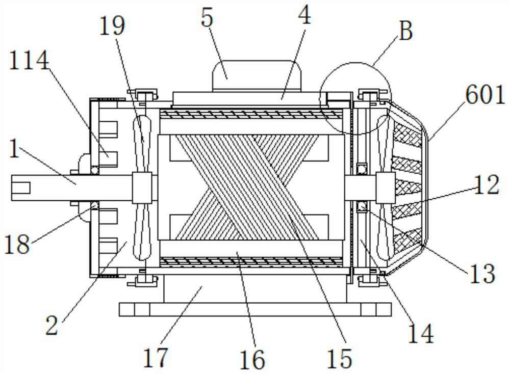
[0035] Example 2, such as figure 1 , 5 As shown, when the rare earth permanent magnet synchronous motor is needed, the four sets of bolts 101 are first united, and since the elastic recovery force of the spring 105 forces the mounting plate 104 and the plurality of sets of lasers 109, the latch 109 is separated. The pin 108 is inside, and then manually pulls the multi-group U-shaped cassette 701, and then pulls the front cover 2 and the rear cover 12 toward one end of the trainer 3 so that the front cover 2 and the rear cover 12 The plug 107 gradually extracts from the inside of the slot 102, thereby completing the removal of the front cover 2 and the rear cover 12, followed by re-installed the front cover 2 and the rear cover 12 after being overhaul inside the motor.

Embodiment 3

[0036] Example 3, such as figure 2 , 3 4, 6, and 7, when the rare earth permanent magnet synchronous motor is used, the motor shaft 1 drives the two sets of fan 19 to rotate, during the operation of the motor, the rotor 15 and the stator winding 16 gradually produce a large amount of heat, the stator The heat of the outer side of the winding 16 gradually passes to the multi-group heat sink A4, and the heat dissipation area is improved by the portion of the heat sink A4, and the heat dissipation effect is improved. The fan 19 rotates so that the outside air is entered from the pass groove A111 into the charm 3 The inside, then the wind blows down on the surface of the rotor 15 and the stator winding 16, and the air with the temperature is passed through the annular thermal conductive sheet 8, and a portion of the heat is transmitted to the outer side of the cabinet 3 on the outer side of the cabinet 3. Thus, the heat transferred by the ring thermally conductive sheet 8 quickly disp...


PUM


Abstract

The invention discloses a self-radiating rare-earth permanent magnet synchronous motor, which comprises a machine compartment. A front machine cover and a rear machine cover are arranged at two ends of the machine compartment respectively, and a filter is provided at the end of the front machine cover far away from the machine compartment. Assemblies, the front machine cover is provided with a bearing B at the center of the end far away from the machine compartment, the end of the inner wall of the machine compartment far away from the front machine cover is evenly provided with connecting rods, and the ends of the connecting rods that are close to each other are jointly provided with bearings A . In the present invention, through the cooperation of the front machine cover, machine compartment, auxiliary components, fixing components and rear machine cover, when the motor is disassembled for maintenance, it is not necessary to remove too many fixing screws, and when installing the front machine cover and the rear machine cover , no need to manually support the front cover and the rear cover to keep the screws aligned with the screw holes, just insert the insert rod into the slot, which greatly improves the convenience of dismounting or installing the motor, and the auxiliary components can further improve The stability of the connection between the front cover and the rear cover and the cabin.

Description

Technical field [0001] The present invention relates to the field of AC motor, in particular a self-refined rare earth permanent magnet synchronous motor. Background technique [0002] The AC permanent magnet synchronous motor is increasingly attracted to people's attention due to its small size, light weight and efficient energy saving, and the starting moment and overload capabilities of rare earth permanent magnet synchronous motors are strong than ordinary synchronous motors. Used in industrial production. [0003] During the use of the rare earth permanent magnet synchronous motor, most of the air in the outside is to cool the motor inside the motor through the gap connected to the front and rear cover, but the gap size between the chair and the front and rear cover is limited. And now there is only one set of fans on the motor shaft inside the synchronous motor, which cannot improve the self-refining effect of the rare earth permanent magnet synchronous motor; and the curre...

Claims


Application Information

Patent Timeline
Patent Type & Authority Patents(China)
IPC IPC(8): H02K5/04H02K5/20H02K9/06H02K5/18H02K9/22H02K5/10H02K9/26
CPCH02K5/04H02K5/10H02K5/18H02K5/20H02K9/06H02K9/22H02K9/26
Inventor 金瓯周洪平
Owner 湖南普东科技有限责任公司
Why Eureka
Try Eureka