Burner for a gas turbine and method for operating the burner

一种燃烧器、燃烧室的技术,应用在燃烧方法、涡轮/推进装置的燃料控制、涡轮/推进燃料输送系统等方向,能够解决影响等问题,达到减少压力波动的效果

Active Publication Date: 2020-10-30
SIEMENS ENERGY GLOBAL GMBH & CO KG
View PDF10 Cites 0 Cited by
  • Summary
  • Abstract
  • Description
  • Claims
  • Application Information

AI Technical Summary

Problems solved by technology

[0006]Even if known solutions make it possible to control the mass flow according to pressure fluctuations, with redundant control actions, especially if pressure sequences above a threshold occur Undesirable effects may occur for certain events where the maximum value of , but does not reflect true combustion conditions

Method used


Image

  • Burner for a gas turbine and method for operating the burner
  • Burner for a gas turbine and method for operating the burner
  • Burner for a gas turbine and method for operating the burner

Examples


Embodiment Construction

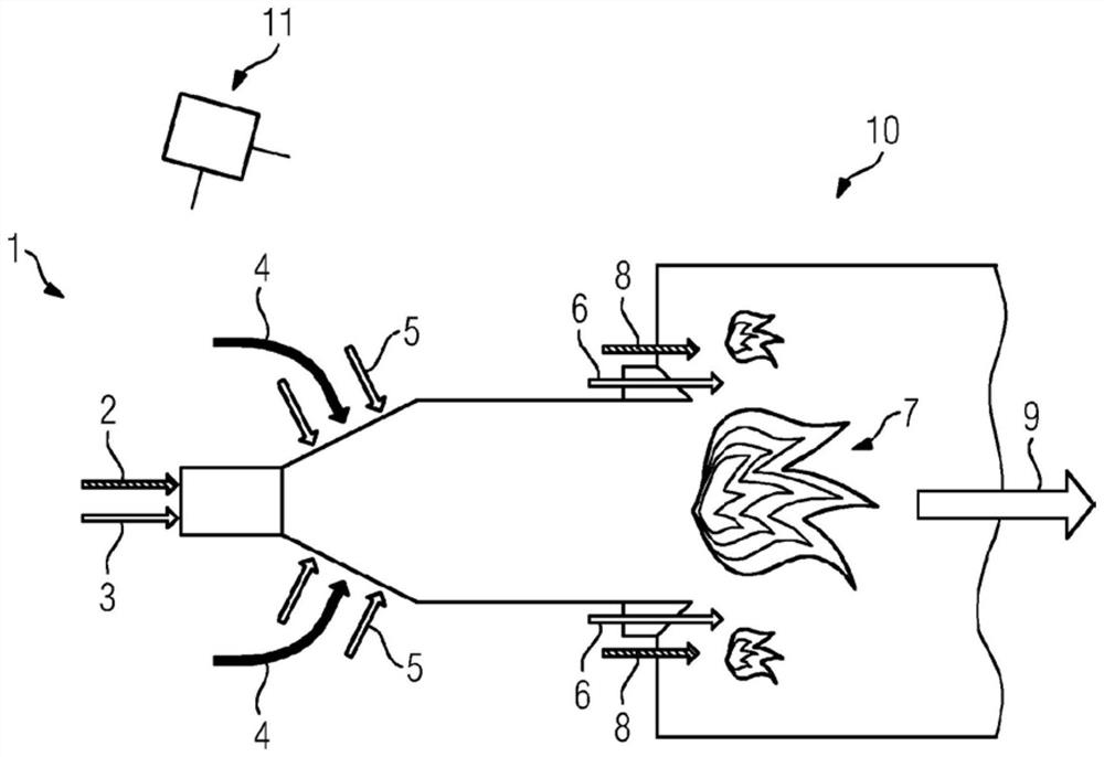
[0035] figure 1 A burner 1 with a combustion chamber 10 , a control unit 11 and fuel stages 2 , 3 , 5 , 6 , 8 is shown. Fuel stages 2 , 3 , 5 , 6 , 8 supply fuel to the combustion chamber 10 . The fuel stages 2 , 3 , 5 , 6 , 8 are a first liquid fuel stage 2 , a first gaseous fuel stage 3 , a second gaseous fuel stage 5 , a third gaseous fuel stage 6 and a second liquid fuel stage 8 . Liquid fuel is supplied to the combustion chamber 10 via liquid fuel stages 2 , 8 and gaseous fuel is supplied to the combustion chamber 10 via gaseous fuel stages 2 , 5 , 6 . Compressed air 4 is also supplied to the combustion chamber 10 . The compressed air 4 is combusted together with fuel in the combustion chamber 10 . exist figure 1 The flame 7 drawn in represents combustion, and the arrow 9 represents the direction of the main flow in the combustion chamber 10 . The control unit 11 is adapted to control the supply of fuel to the combustion chamber 10 via at least one of the fuel stages...


PUM


Abstract

The invention relates to a burner (1) with a control unit (11), a combustion chamber (10), a pressure sensor and fuel stages (2, 3, 5, 6, 8) which are arranged to supply fuel with a respective mass flow to the combustion chamber (10), wherein the mass flows are controlled by the control unit (11), wherein the pressure sensor is adapted to measure a pressure sequence (14) in the combustion chamber(10) or in the burner (1) and to transfer the pressure sequence (14) to the control unit (11) which is adapted to perform a Fourier transformation on at least one determined timespan (t1, t2, t3, t4)of the pressure sequence (14) to result in a pressure spectrum (27, 28, 29, 30) having a maximum (31, 32, 33, 34) within a frequency band (24) and wherein the control unit (11) is adapted to perform acomparison of the maximum (31, 32, 33, 34) with a predefined threshold (26) and to control the mass flows by using the comparison to reduce and / or to control pressure fluctuations in the combustion chamber (10).

Description

technical field [0001] The invention relates to a combustor for a gas turbine and a method for operating the combustor. Background technique [0002] Combustors for gas turbines are conventionally designed for specific operating conditions, such as specific fuel compositions and specific fuel pressures. If a conventional gas turbine is operated under specific operating conditions for which the gas turbine and combustor are conventionally designed, both the emissions of the gas turbine and the operational availability of the gas turbine are within its planned range. [0003] But during the operation of a gas turbine on site, the specific operating conditions may vary in different ranges. The ambient temperature may for example vary from -50°C to +50°C or during operation of the gas turbine the properties of the fuel such as fuel pressure, fuel temperature, fuel composition or fuel quality may change or vary. [0004] It is known that varying operating conditions can lead to...

Claims


Application Information

Patent Timeline
Patent Type & Authority Applications(China)
IPC IPC(8): F23N1/00F23N5/16F23R3/34
CPCF23N1/002F23N5/16F23R3/34F23N2223/06F23N2225/04F23N2241/20F02C7/22F02C9/28F23R3/005F23R3/28F23R2900/00013
Inventor P·盖佩尔A·林德霍姆R·马格努松A·曼里克·卡雷拉
Owner SIEMENS ENERGY GLOBAL GMBH & CO KG
Why Eureka
Try Eureka