
Ultrasonic anti-pollution detachable ultrafiltration membrane system

An ultrafiltration membrane and anti-pollution technology, applied in the field of ultrafiltration membrane systems, can solve the problems of reducing the filtration effect of the device, easy to contaminate and block the membrane surface, inconvenient to replace the ultrafiltration membrane, etc. The effect of increasing water production

Active Publication Date: 2020-11-03
ENERGY RES INST OF JIANGXI ACAD OF SCI
View PDF6 Cites 3 Cited by
  • Summary
  • Abstract
  • Description
  • Claims
  • Application Information

AI Technical Summary

Problems solved by technology

[0003] However, during the long-term use of the ultrafiltration membrane, because the membrane surface is easily polluted and blocked, the membrane flux is reduced, the filtration effect of the device is reduced, and the service life of the membrane is greatly shortened. Therefore, the ultrafiltration membrane needs to be replaced regularly. However, the traditional ultrafiltration membranes are often integrated, which is inconvenient to replace the ultrafiltration membranes, and the existing backwash cleaning method requires a certain reserve of effluent, which is not conducive to the development of cleaning operations. Therefore, a new method is proposed. An Ultrasonic Anti-Pollution Detachable Ultrafiltration Membrane System

Method used


Image

  • Ultrasonic anti-pollution detachable ultrafiltration membrane system
  • Ultrasonic anti-pollution detachable ultrafiltration membrane system
  • Ultrasonic anti-pollution detachable ultrafiltration membrane system

Examples


Embodiment Construction

[0024] The following will clearly and completely describe the technical solutions in the embodiments of the present invention with reference to the accompanying drawings in the embodiments of the present invention. Obviously, the described embodiments are only some, not all, embodiments of the present invention.

[0025] In describing the present invention, it should be understood that the terms "upper", "lower", "front", "rear", "left", "right", "top", "bottom", "inner", " The orientation or positional relationship indicated by "outside", etc. is based on the orientation or positional relationship shown in the drawings, and is only for the convenience of describing the present invention and simplifying the description, rather than indicating or implying that the referred device or element must have a specific orientation, so as to Specific orientation configurations and operations, therefore, are not to be construed as limitations on the invention.

[0026] refer to Figure ...


PUM

PropertyMeasurementUnit
pore sizeaaaaaaaaaa

Abstract

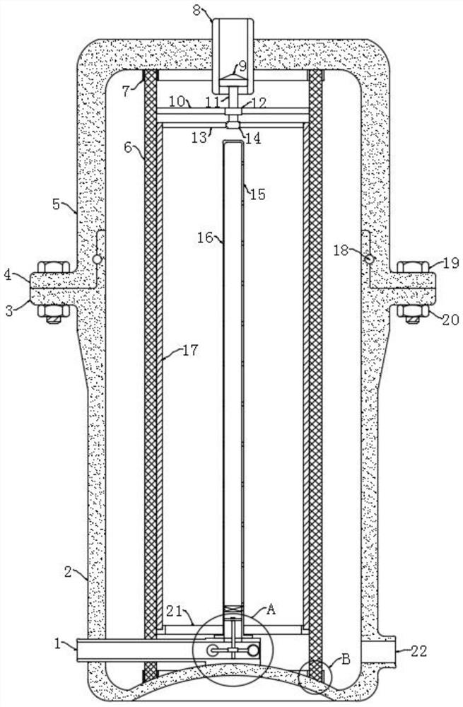
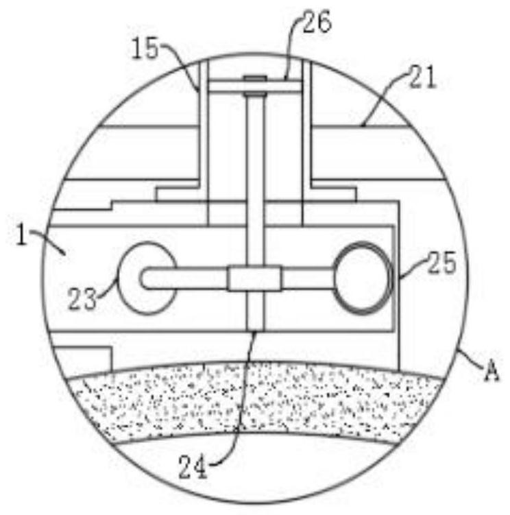
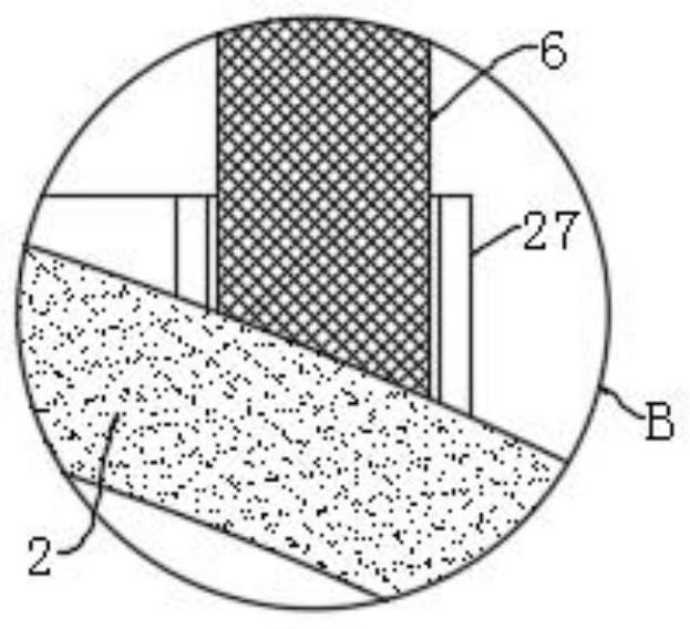
The invention discloses an ultrasonic anti-pollution detachable ultrafiltration membrane system, which comprises an upper shell and a lower shell arranged below the upper shell, wherein the upper shell and the lower shell are fixedly connected through a mounting mechanism, a filter cavity is formed between the upper shell and the lower shell, and a mounting ring is fixedly connected to the inner top of the upper shell; a positioning ring is fixedly connected to the inner bottom of the lower shell, an ultrafiltration membrane core used for filtering and purifying water is arranged between the positioning ring and the mounting ring, a water inlet is formed in the middle of the upper shell in a penetrating mode, and a cleaning mechanism used for cleaning the ultrafiltration membrane core is arranged in the water inlet. The ultrafiltration membrane system is reasonable in structural design, wherein the scraper blade can be driven in a hydraulic mode, so that impurities are convenient to clean; the cleaning pipe is driven to rotate and spray out in a wind power mode, the impurities on the fiber membrane core of the ultrafiltration membrane are conveniently and fully blown off; the ultrafiltration membrane system is convenient to assemble and disassemble through the arrangement of the installation mechanism.

Description

technical field [0001] The invention relates to the technical field of ultrafiltration membrane systems, in particular to an ultrasonic anti-pollution detachable ultrafiltration membrane system. Background technique [0002] The ultrafiltration membrane is used for artificial permeation in the ultrafiltration process. It is generally made of polymer materials such as cellulose acetate, cellulose acetate ester, polyethylene, polysulfone and polyamide. Generally, various types of membrane modules such as tube type, plate type, roll type, and capillary type are prefabricated, and then assembled and used together to increase the filtration area and facilitate maintenance. The ultrafiltration membrane is a polymer semipermeable membrane used in the ultrafiltration process to separate polymer colloids or suspended particles of a certain size from the solution. With pressure as the driving force, the membrane pore size is 1-100nm, which belongs to the asymmetric membrane type. T...

Claims


Application Information

Patent Timeline
Patent Type & Authority Applications(China)
IPC IPC(8): B01D61/18B01D61/20B01D65/04C02F1/44
CPCB01D61/145B01D61/18B01D61/20B01D65/02B01D2321/18B01D2321/30C02F1/444C02F2201/002C02F2201/004C02F2303/14
Inventor 桂双林熊继海姜钦亮吴九九麦兆环付嘉琦
Owner ENERGY RES INST OF JIANGXI ACAD OF SCI
Learn More