Centrifugal mud dehydrator and dehydration treatment method

A centrifugal and dehydrator technology, applied in water/sludge/sewage treatment, centrifuge, sludge treatment and other directions, which can solve the problems of reducing the radius of the filter hole, affecting the efficiency of mud-water separation, and insufficient mud separation. , to achieve the effect of ensuring cleanliness

Inactive Publication Date: 2020-11-03
吴迎莉
View PDF9 Cites 3 Cited by
  • Summary
  • Abstract
  • Description
  • Claims
  • Application Information

AI Technical Summary

Problems solved by technology

[0003] However, the centrifugal mud dewatering machines currently on the market have the following problems during use, a. Because the sludge particles in the mud are thrown out at high speed during the use of the traditional centrifugal mud dewatering machines, some sludge particles will adhere Around the filter hole, the effect radius of the filter hole is reduced, which affects the separation efficiency in the mud water. In severe cases, the filter hole will be blocked, resulting in the separation process cannot be performed normally; b. The existing centrifugal mud dewatering machines all use Placed horizontally, so that after the separation of the mud, part of the water in the mud remains in the centrifugal cylinder, resulting in insufficient separation of the mud

Method used


Image

  • Centrifugal mud dehydrator and dehydration treatment method
  • Centrifugal mud dehydrator and dehydration treatment method
  • Centrifugal mud dehydrator and dehydration treatment method

Examples


Embodiment Construction

[0031] In order to make the technical problems, technical solutions and beneficial effects to be solved by the present invention clearer, the present invention will be further described in detail below in conjunction with the accompanying drawings and embodiments. It should be understood that the specific embodiments described here are only used to explain the present invention, not to limit the present invention.

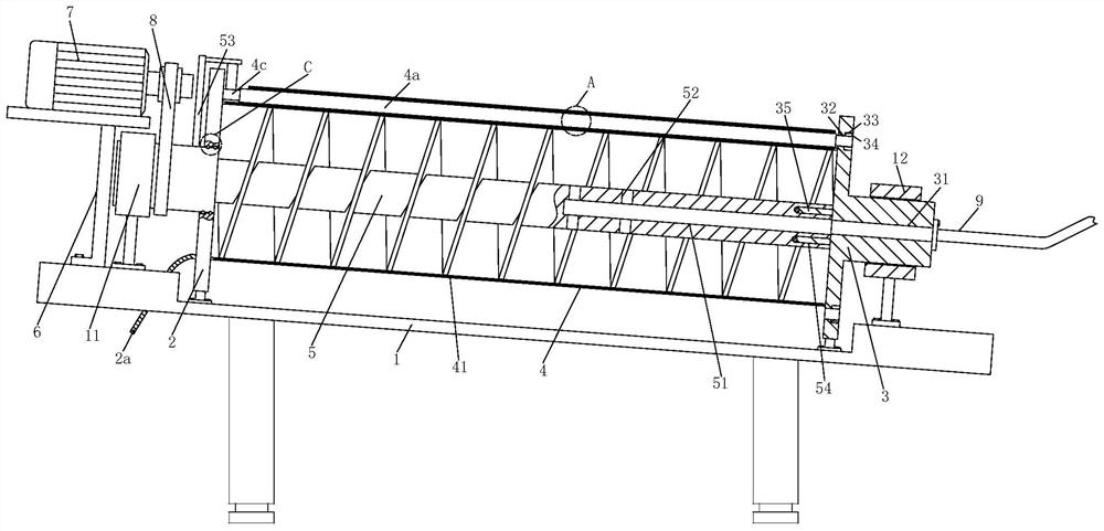
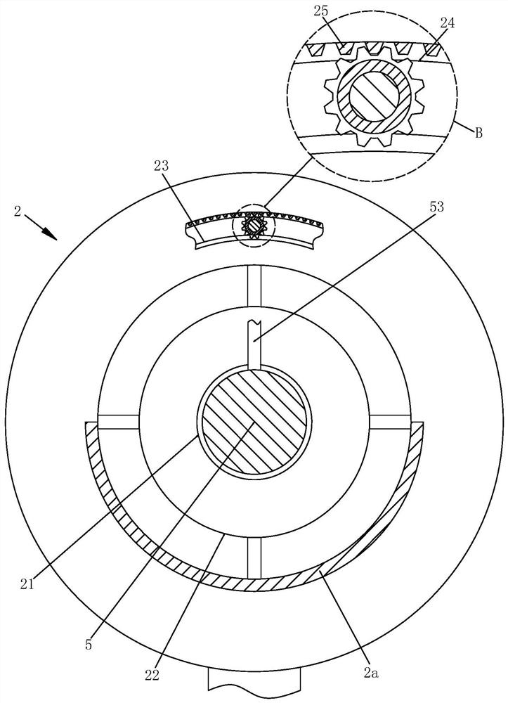
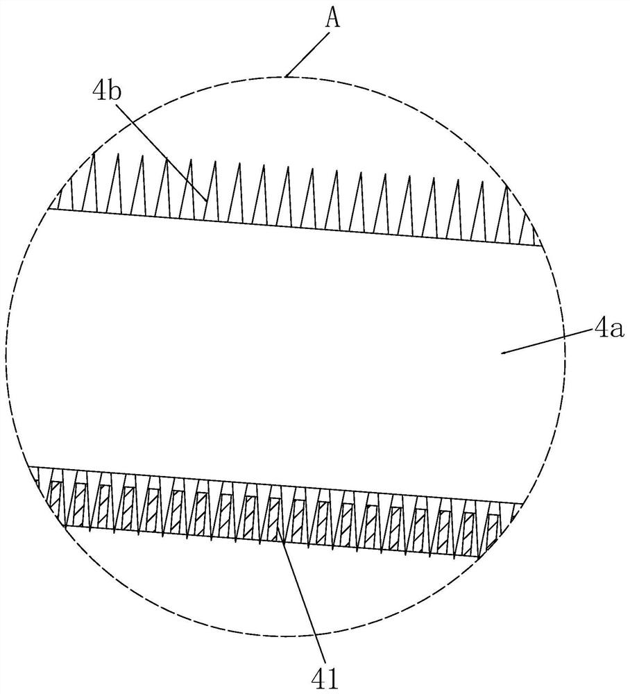
[0032] Such as Figure 1 to Figure 5 As shown, a centrifugal mud dehydrator includes a support base 1, a first support disc 2, a second support disc 3, a centrifugal cylinder 4, a screw feed rod 5, a motor frame 6, a drive motor 7, The transmission belt 8 and the feed pipe 9, the top of the support base 1 is provided with a rectangular groove, the first supporting disc 2 is installed at one end of the rectangular groove, and the second supporting disc is installed at the other end of the rectangular groove 3. The centrifugal cylinder 4 is located between the first...


PUM


Abstract

The invention relates to a centrifugal mud dehydrator and a dehydration treatment method. The dehydrator comprises a supporting base, a first bearing disc, a second bearing disc, a centrifugal barrel,a spiral feeding rod, a motor frame, a driving motor, a transmission belt and a feeding pipe, wherein a rectangular groove is formed in the top of the supporting base, the first bearing disc is arranged at one end of the interior of the rectangular groove, the second supporting disc is arranged at the other end of the interior of the rectangular groove, the centrifugal barrel is located between the first supporting disc and the second supporting disc, the two ends of the centrifugal barrel are fixed to the side wall of the first supporting disc and the side wall of the second supporting discin a welded mode, the spiral feeding rod is arranged in the center of the interior of the centrifugal barrel, one end of the spiral feeding rod is arranged at the interior of the first bearing disc, the other end of the spiral feeding rod is arranged on the second bearing disc, and the center of the other end of the second bearing disc is connected with the feeding pipe. The dehydrator has the characteristic of automatically cleaning filter holes, and is more sufficient in mud separation compared with a traditional separation machine.

Description

technical field [0001] The invention relates to the technical field of sewage treatment, in particular to a centrifugal mud dehydrator and a dehydration treatment method. Background technique [0002] Slurry concentration mainly refers to the use of gravity to effectively increase the solid content of the mud. If the gravity concentration tank is used to treat the sewage, it will take a lot of time, and the organic matter in the sewage will be corrupted and smelly due to the action of microorganisms. Seriously affect the sanitation of sewage treatment plants. Therefore, in the actual treatment process, after using the gravity concentration tank to reduce the water content of the sludge to 94% to 96%, it is necessary to use the sludge dehydration equipment to reduce the water content of the sludge to below 80%, so as to facilitate the later stage. Transport and disposal work. The current common sludge dewatering equipment includes belt filter press dewatering machine, centr...

Claims


Application Information

Patent Timeline
Patent Type & Authority Applications(China)
IPC IPC(8): B04B1/20B04B15/06C02F11/127
CPCB04B1/20B04B15/06C02F11/127
Inventor 吴迎莉
Owner 吴迎莉
Why Eureka
Try Eureka