Automatic wheel set painting device
An automatic brushing and wheel setting technology, applied in the direction of spraying device, liquid spraying device, etc., can solve problems such as insolvency, low efficiency, health hazards of employees, etc., to achieve more uniform painting, avoid waste of resources, and improve painting efficiency. Effect
- Summary
- Abstract
- Description
- Claims
- Application Information
AI Technical Summary
Problems solved by technology
Method used
Image
Examples
Embodiment 1
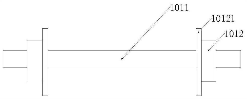
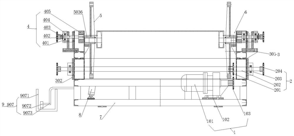
[0064] Such as figure 2 , figure 2 A structural schematic diagram of an automatic wheel set painting device provided in Embodiment 1 of the present invention; an automatic wheel set painting device, including a first driving mechanism 1, a rotating mechanism 2, a fixing assembly 3, and a wheel set rolling mechanism 4; Rocker arm assembly 5, chute 6, frame structure 7, second driving mechanism 8 and painting device 9; wherein:
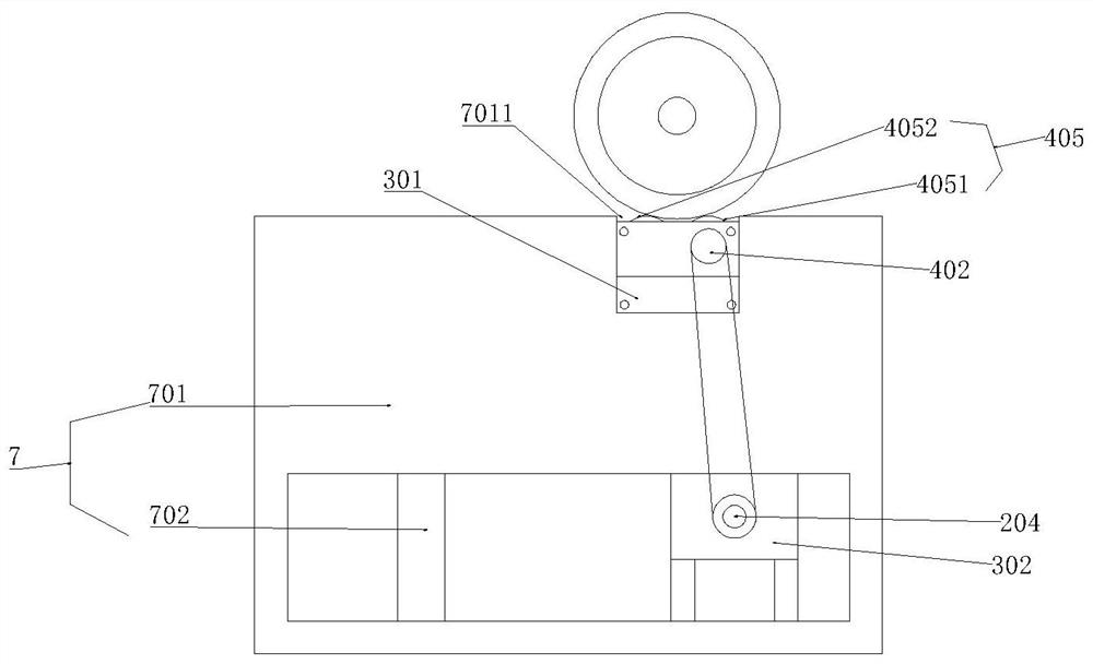
[0065] Both sides of the top of the frame structure 7 are symmetrically provided with chute 6 for accommodating wheelsets; the bottom bolt of the frame structure 7 is fixedly provided with a first drive mechanism 1, and the first drive mechanism 1 and the The rotating mechanism 2 on the frame structure 7 is connected and drives the rotating mechanism 2 to rotate; the fixed assembly 3 is fixed on the side of the frame structure 7 and supports the wheel pair rolling mechanism 4; the wheel pair rolling mechanism 4 is connected to the rotating mechanism ...
Embodiment 2
[0100] refer to Figure 13 , Figure 13 A schematic circuit diagram of a wheel set automatic painting device provided in an embodiment of the present invention; the present invention also includes a painting control circuit, the painting control circuit includes a chip control module and a motor control module, and the chip control module and Electrical connection of the motor control module;
[0101] The model of the chip control module is CP1E-E40SDR-A; the L1 pin of the chip control module is connected to the neutral line N;
[0102] Wherein, the motor control module includes a button switch S0, a fuse FU1, a fuse FU2, a fuse FU3, an AC contactor KM0, an AC contactor KM1, an AC contactor KM2, a motor M1, and a motor M2. KM0 includes a coil KM01 and a normally open contact KM02; the AC contactor KM1 includes a coil KM11 and a normally open contact KM12; the AC contactor KM2 includes a coil KM21 and a normally open contact KM22; wherein the live line L3 and One end of the ...
Embodiment 3
[0110] refer to Figure 12 , Figure 12 The pneumatic principle diagram of a wheel set automatic painting device provided by the embodiment of the present invention; also includes a pneumatic system, the pneumatic system includes a pneumatic triple piece, an electromagnetic reversing valve Y1, an electromagnetic reversing valve Y2, an electromagnetic reversing valve Y3; wherein, the pneumatic triple piece is respectively connected with the air inlet P1 of the electromagnetic reversing valve Y1, the air inlet P2 of the electromagnetic reversing valve Y2, and the air inlet P3 of the electromagnetic reversing valve Y3;
[0111] The air outlet A1 of the electromagnetic reversing valve Y1 is connected to the air inlet of a group of lifting cylinders 901; the air outlet of the lifting cylinder is connected to the air inlet B1 of the electromagnetic reversing valve Y1.
[0112] The air outlet A2 of the electromagnetic reversing valve Y2 communicates with the air inlets of a group of...
PUM
 Abstract
Description
Claims
Application Information
 - R&D
- Intellectual Property
- Life Sciences
- Materials
- Tech Scout
- Unparalleled Data Quality
- Higher Quality Content
- 60% Fewer Hallucinations
Browse by: Latest US Patents, China's latest patents, Technical Efficacy Thesaurus, Application Domain, Technology Topic, Popular Technical Reports.
© 2025 PatSnap. All rights reserved.Legal|Privacy policy|Modern Slavery Act Transparency Statement|Sitemap|About US| Contact US: help@patsnap.com


