
A new joint bolt forming device

A molding device, a new type of technology, applied in the direction of feeding device, positioning device, quenching device, etc., to achieve the effect of reducing heat flow rate, avoiding work, and reducing a large amount of workload

Active Publication Date: 2021-01-22
SHENGJIAN NO 83 FACTORY SHANDONG PROV
View PDF4 Cites 0 Cited by
  • Summary
  • Abstract
  • Description
  • Claims
  • Application Information

AI Technical Summary

Problems solved by technology

[0004] The purpose of the invention is to solve the above problems. This application provides a new type of joint bolt forming device, which solves the problem that the existing processing projects are carried out separately and part of the heat flow rate

Method used


Image

  • A new joint bolt forming device
  • A new joint bolt forming device
  • A new joint bolt forming device

Examples


Embodiment

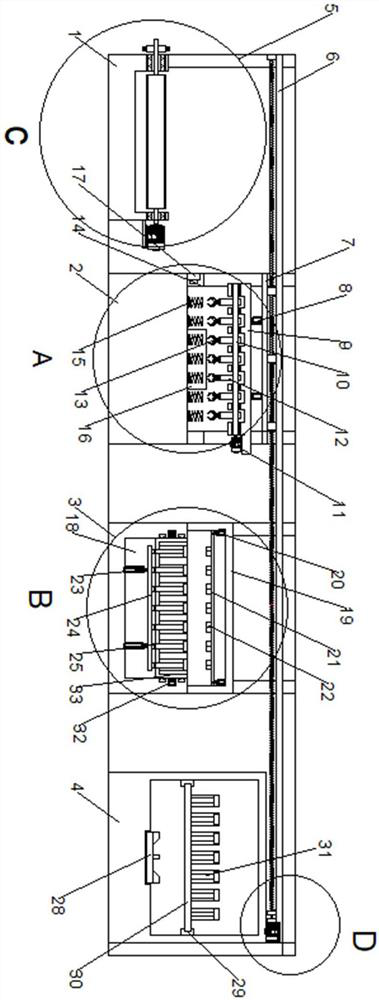
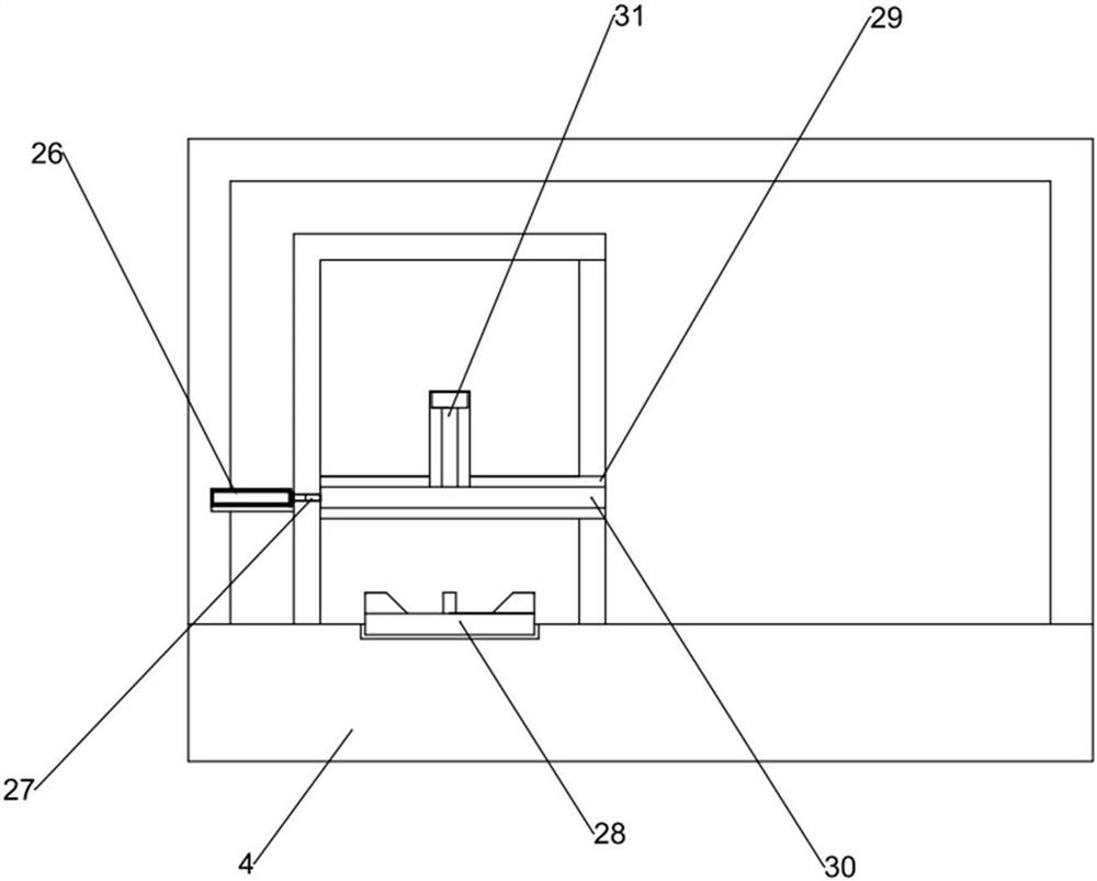
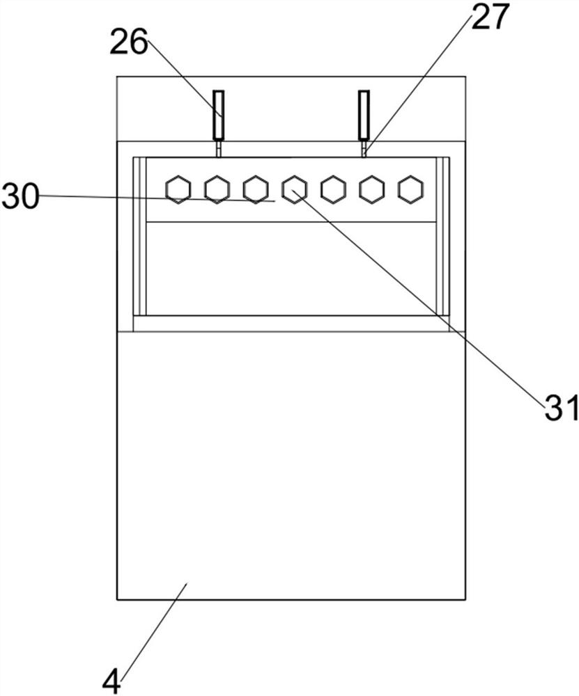
[0035] Embodiment: through the operation of a pair of horizontal lead screw modules 6, the horizontal moving plate 7 on the moving end of the pair of horizontal lead screw modules 6 is driven to move horizontally, and the two pairs of telescopic multi-stage hydraulic pushers on it are driven by the horizontal moving plate 7. Rod 8, toothed box 9, several transport rods 12 and several transport claws 13 are brought above the transport platform 1, stretched by two pairs of telescopic multi-section hydraulic push rods 8, and driven by the transport drive 11 to drive the drive on the drive end. The shaft 10 drives several conveying rods 12 to rotate through the drive shaft 10, so that several conveying rods 12 form a 90-degree angle with several steel raw materials, and the raw materials are picked up by several conveying claws 13 on several conveying rods 12. Two pairs of telescopic multi-segment hydraulic push rods 8 are contracted, and the two pairs of telescopic multi-segment h...


PUM


Abstract

The invention discloses a novel joint bolt forming device. The device comprises a conveying table, a heat conduction table, an extrusion table, a combustion box and a carrying support, the carrying support is installed on the conveying table, the heat conduction table, the extrusion table and the combustion box, an electric heating structure is installed on the heat conduction table, and an extrusion structure is installed on the extrusion table. A quenching structure is installed in the combustion box, and a carrying structure is installed on the carrying support. The device has the beneficial effects that raw materials are rapidly converted among the electric heating structure, the extrusion structure and the quenching structure through the carrying structure, a large amount of workloadof manual operation is reduced, meanwhile, the heat flow rate phenomenon occurring in the machining process is reduced, and the multiple raw materials are carried in sequence through the carrying structure; and the phenomenon of misoperation in the carrying process is avoided, and meanwhile manual work in the high-temperature environment is avoided.

Description

technical field [0001] The invention relates to the technical field of bolt processing, in particular to a novel joint bolt forming device. Background technique [0002] The production process of bolts, especially high-strength bolts, mainly includes: raw material blanking, bolt forming, heat treatment (generally quenching + high temperature tempering), surface anti-corrosion treatment and other important steps. [0003] In the existing production process of high-strength bolts, the current problems are: firstly, the bolt forming, heat treatment, and surface treatment of domestic manufacturers are carried out separately, not in the same workshop or the same manufacturer, which greatly increases the transportation cost. Secondly, the equipment and capacity for heat treatment (quenching and tempering) are fixed, inflexible, and unfavorable for continuous processing in the state of production volume changes. Contents of the invention [0004] The purpose of the invention is ...

Claims


Application Information

Patent Timeline
Patent Type & Authority Patents(China)
IPC IPC(8): B21D22/02B21D43/10B21D45/02B21D53/24C21D9/00C21D1/63
CPCB21D22/02B21D22/022B21D43/105B21D45/02B21D53/24C21D1/63C21D9/0093
Inventor 刘炳强唐永贵赵利利高长城侯海军张繁秋
Owner SHENGJIAN NO 83 FACTORY SHANDONG PROV
Learn More