Compact and firm multi-degree-of-freedom bionic joint and manufacturing method thereof

A bionic joint and manufacturing method technology, applied in the field of robotics, can solve problems such as large joint volume, material fatigue, deformation, etc., and achieve the effects of simple joint structure, high impact resistance, and reduced manufacturing costs.

Pending Publication Date: 2020-11-03
蔡世勋
View PDF21 Cites 0 Cited by
  • Summary
  • Abstract
  • Description
  • Claims
  • Application Information

AI Technical Summary

Problems solved by technology

[0009] First, the shaft and bushing bear pressure and tension at the same time. In order to ensure the structural strength, the joint volume is large and the manufacturing cost is high
[0010] Second, for mechanical structures containing multi-joints, such as in robot hands, shoulders, and hip joints, the structure of the joint itself takes up too much space. resettlement difficulties
[0011] Third, the joints are made of hard materials, and when subjected to external impacts, the local load is large, which easily causes material fatigue and deformation, which in turn causes component failure
[0020] First, some adopt deep ball-socket schemes, which lead to interference between the ball head and the edge of the ball-socket, and the range of joint motion is limited; others adopt shallow ball-socket schemes, and the shape of the connecting parts is sleeve-shaped or sheet-shaped, and the joints are not smooth. Stable, weak tensile strength, large displacement of the joint head, easy to fall out of the joint socket
[0021] Second, soft braided materials or other elastic materials are used to make joint connectors, resulting in poor joint stability and weak joint tensile capacity. There is a large gap in the joint under the condition of bearing tangential force, torsional force and tensile force. poor precision
[0022] Third, use a hard and flexible sheet material, such as a rubber sheet, to make the connector. When the joint rotates, the sheet material bends. This deformation produces a resistive moment, consumes energy, and leads to poor mobility
[0023] Fourth, screws, surface bonding, ring clips, etc. are used to connect and fix the connectors and structural parts, which have low strength, poor tear-off resistance, and poor impact resistance
[0024] Fifth, the large number of parts and many assembly and adjustment steps are not conducive to the adoption of standardized manufacturing processes, resulting in high manufacturing costs and low manufacturing efficiency

Method used


Image

  • Compact and firm multi-degree-of-freedom bionic joint and manufacturing method thereof
  • Compact and firm multi-degree-of-freedom bionic joint and manufacturing method thereof
  • Compact and firm multi-degree-of-freedom bionic joint and manufacturing method thereof

Examples


Embodiment 1

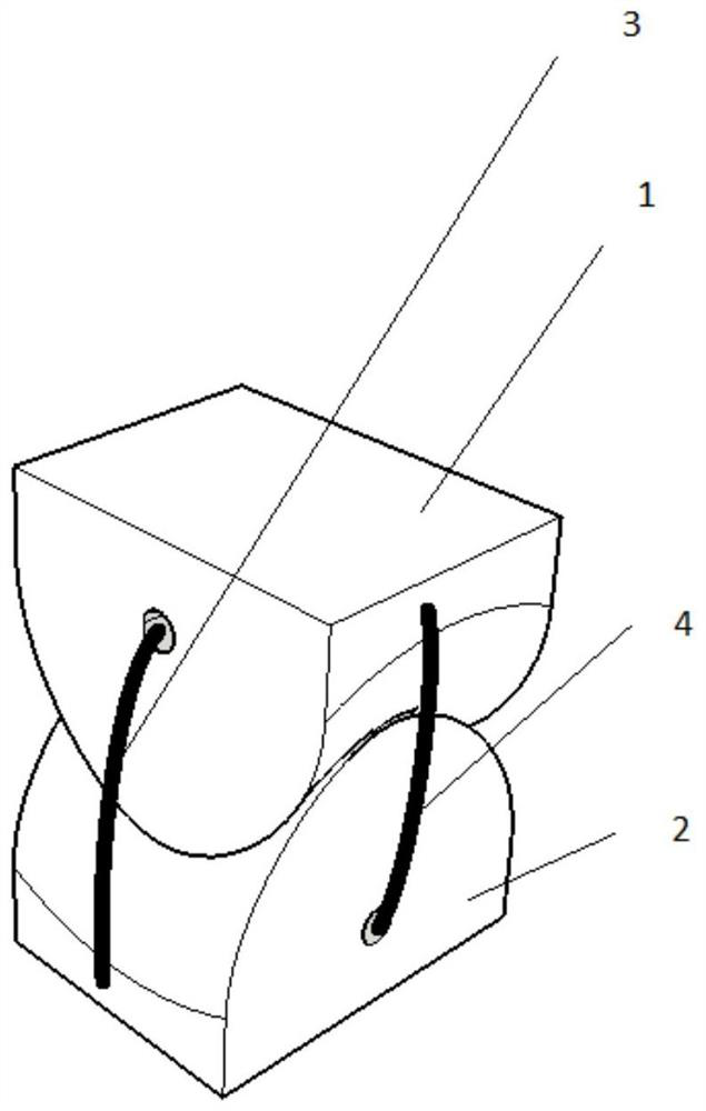
[0054] Reference attached figure 1 and attached figure 2 , showing a 2-DOF biomimetic joint. attached figure 1 is an exploded diagram, with figure 2 is a stereogram.

[0055] The first joint 1 includes a first curved surface 11, a first installation hole 12 in the X direction, and a first installation hole 13 in the Y direction. The first installation hole 12 in the X direction is located at the axis of the curved surface, and the first installation hole 13 in the Y direction is located at the outer edge of the curved surface. ;

[0056] The second joint member 2 includes a second curved surface 21, a second installation hole 23 in the X direction, and a second installation hole 22 in the Y direction. The second installation hole 22 in the X direction is located at the axis of the second curved surface 21, and the second installation hole 23 in the Y direction is located the outer edge of the second curved surface 22;

[0057] The X-direction connecting fiber 3 passes ...

Embodiment 2

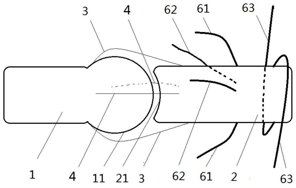
[0062] Reference attached image 3 , showing a 3-DOF bionic joint.

[0063] The first joint member 1 includes a first curved surface 11, and the first curved surface 11 is a convex spherical surface.

[0064] The second joint member 2 includes a second curved surface 21, and the second curved surface 21 is a concave spherical surface.

[0065] The X-direction connecting fibers 3 and Y-direction connecting fibers 4 connect the first joint part 1 and the second joint part 2 .

[0066] When the first joint part 1 rotates relative to the second joint part 2, the X-direction connecting fibers 3 and Y-direction connecting fibers 4 tighten the first curved surface 11 and the second curved surface 21 to ensure the accuracy of the motion trajectory, while defining The range of rotation of the joint.

[0067] The X-direction connecting fiber 3 and the Y-direction connecting fiber 4 are manufactured by mixing 70% Kevlar fiber and 30% elastic polyurethane fiber material, so that the co...

Embodiment 3

[0070] Reference attached Figure 4 , shows the schematic diagram of the motion of the bionic joint with variable degrees of freedom.

[0071] attached Figure 4 It is shown that the limiting fiber 7 is tightened as the second joint member 2 rotates. Adding a limit fiber 7 between the first joint part 1 and the second joint part 2 can further limit the degree of freedom of joint movement. The connection position between the limiting fiber 7 and the first curved surface 11 deviates from the axis of the first curved surface 11, and the connection position with the second joint part 2 is located near the edge of the second curved surface 21. When the second joint part 2 gradually rotates clockwise, The limiting fiber 7 is gradually tightened from the relaxed state, restricting the second joint member 2 from further clockwise rotation and lateral swinging, and at this time the degree of freedom of the joint is reduced.


PUM


Abstract

The invention discloses a compact and firm multi-degree-of-freedom bionic joint which comprises a first joint piece, a second joint piece, X-direction connecting fibers and Y-direction connecting fibers; and the end of the first joint piece is a first curve face, and the end of the second joint piece is a second curve face matched with the first curve face. The compact and firm multi-degree-of-freedom bionic joint has the beneficial effects that firstly, the compact and firm multi-degree-of-freedom bionic joint is simple in joint structure, small in size, light in weight, high in strength andthe like, the impact resistance is high, and the stress of a connecting piece when the joint is bent is reduced; and secondly, the compact and firm multi-degree-of-freedom bionic joint is small in gapand high in motion precision under the stress condition, meanwhile, the whole bionic joint is convenient to manufacture through an automatic process, the manufacturing efficiency is improved, and themanufacturing cost is reduced.

Description

technical field [0001] The invention relates to the technical field of robots, in particular to a compact and firm multi-degree-of-freedom bionic joint and a manufacturing method thereof. Background technique [0002] A joint is a common part in a mechanical structure. Its basic functions include: bearing radial and tangential forces, including tensile, compressive and torsional forces; limiting the degree of freedom of mechanical motion, that is, limiting the direction and range of motion. [0003] The existing sleeve-type joint adopts a rigid shaft and a sleeve as a design scheme, and the joint has good stability and high motion precision. For example: [0004] Patentee DISNEY ENTERPRISES, INC.'s invention "ROBOT HAND WITH HUMAN-LIKEFINGERS" (US20100259057A1); [0005] Patentee GM Global Technology Operations LLC's invention "robotic thumbassembly" (US8424941); [0006] The patentee SQUSE Inc.'s invention "finger mechanism, robot hand and robot hand controlling method" ...

Claims


Application Information

Patent Timeline
Patent Type & Authority Applications(China)
IPC IPC(8): B25J17/00B25J9/10
CPCB25J17/00B25J9/104
Inventor 蔡世勋
Owner 蔡世勋
Why Eureka
Try Eureka