
Automatic coil-unloading and shaft-loading device and automatic coil-unloading and shaft-loading method

A technology of automatic unloading and shaft device, which is applied in the directions of winding strips, transportation and packaging, thin material processing, etc. It can solve the problems of long time consumption, low degree of automation, and heavy film roll weight, so as to reduce labor intensity and automatically high degree of effect

Active Publication Date: 2020-11-03
GUANGDONG JINMING MACHINERY
View PDF6 Cites 6 Cited by
  • Summary
  • Abstract
  • Description
  • Claims
  • Application Information

AI Technical Summary

Problems solved by technology

However, the above-mentioned unloading trolley is only suitable for the film roll unloading process involving the paper core tube winding method, but not suitable for the film roll unloading process of the optical axis winding method, which is the result of the joint action of the following factors : First, the weight of the film roll is heavy, and the top panel of the unloading trolley bears a large load when carrying the film roll, which means that the power mechanism that drives the top panel of the unloading trolley to rise is a hydraulic mechanism with a large force; The weight of the roll is heavy, so when the film roll is transferred from the winding stand to the top panel of the unloading trolley, the top panel of the unloading trolley must be in close contact with the lower surface of the film roll, that is, there should be no vertical gap between the two. Otherwise, the film roll will have a free fall stroke, which will generate large vibrations, and even impact and damage the unloading trolley; third, due to the large difference in the winding diameter of various film materials, the above power mechanism In the rising process of driving the top panel of the unloading trolley, it is actually impossible to stop the power output just when it touches the surface of the film roll, but generally in order to ensure that the top panel of the unloading trolley closely contacts the lower surface of the film roll, the hydraulic mechanism must It will strongly impact the lower surface of the film roll upwards; for the paper core tube winding method, due to the gas buffering effect of the air expansion shaft and the paper layer buffering effect of the paper core tube, this upward impact is transmitted to the two sides of the winding shaft. However, for the optical axis winding method, due to the absence of the gas buffering effect of the air shaft and the buffering effect of the paper layer of the paper core, the tightly wound plastic film roll has a high hardness. Therefore, this upward impact force will be greatly transmitted to both ends of the winding shaft, and then damage the plug connected to the end of the winding shaft and the winding power mechanism (winding motor)
[0008] Therefore, for the optical axis winding method, in the prior art, the unloading and winding process after winding is not suitable for unloading trolleys with traditional structures, which mainly rely on manual work, with low automation and high labor intensity. time consuming

Method used


Image

  • Automatic coil-unloading and shaft-loading device and automatic coil-unloading and shaft-loading method
  • Automatic coil-unloading and shaft-loading device and automatic coil-unloading and shaft-loading method
  • Automatic coil-unloading and shaft-loading device and automatic coil-unloading and shaft-loading method

Examples


Embodiment 1

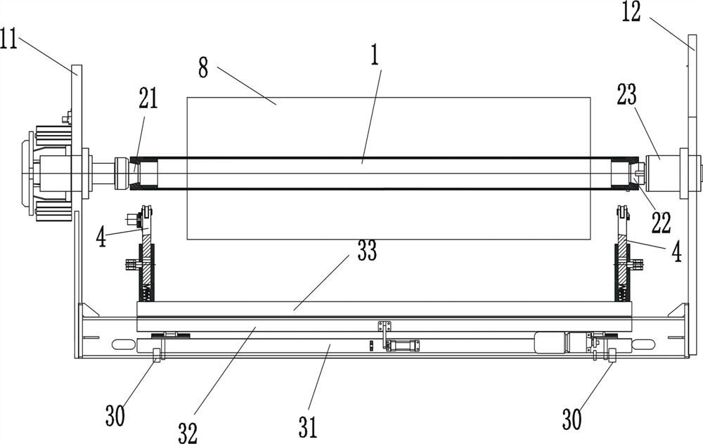
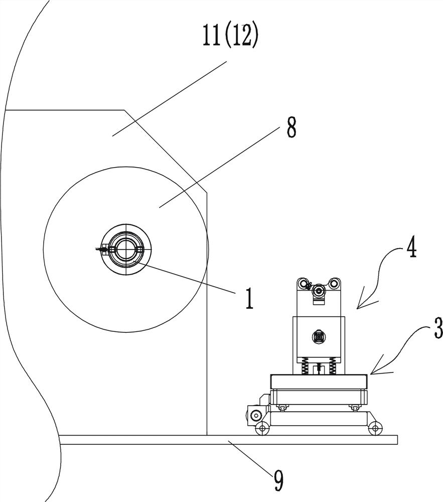
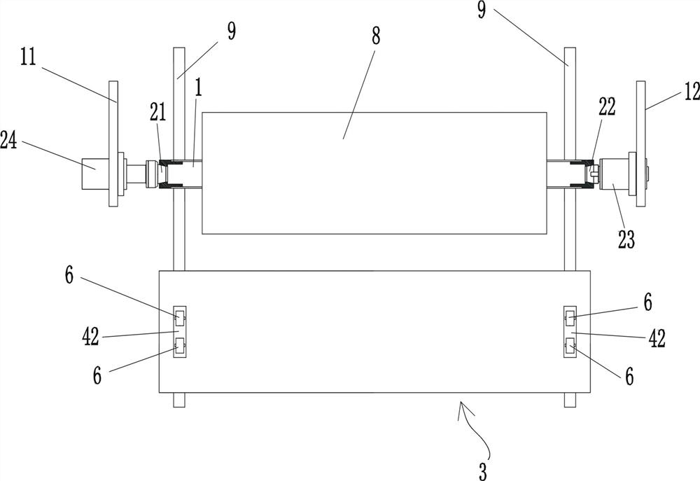
[0066] figure 1 , figure 2 , image 3 As shown, the automatic unwinding shaft device includes a winding shaft 1, a winding support 11 located on the left side of the winding shaft, and a winding support 12 located on the right side of the winding shaft. The central axis of the winding shaft 1 extends laterally, and the left The winding bracket 11 on the side is rotatably equipped with a left plug 21 , and the winding bracket 12 on the right side is rotatably equipped with a right plug 22 . Figure 8 , Figure 9 , Figure 10 , Figure 11 As shown, the left and right ends of the winding shaft 1 are respectively provided with tapered sockets 10, and the tapered sockets 10 at the two ends of the winding shaft respectively form a movable plugging relationship with the plugs on the corresponding sides. The axial direction of the reel 1; the rewinding shaft bracket 12 on the right is also provided with a winding motor 23 that drives the right plug to rotate, and the winding sha...

Embodiment 2

[0071] A method for an automatic unloading and winding device, which adopts the automatic unloading and winding device of the first embodiment, and sequentially includes the following steps:

[0072] (1) For normal rewinding, the left plug 21 is inserted into the tapered socket 10 at the left end of the winding shaft, the right plug 22 is inserted into the tapered socket 10 at the right end of the winding shaft, the spline block of the right plug 25 is embedded in the keyway 26 at the right end of the winding shaft, the winding motor 23 drives the right plug 22 to rotate, the right plug 22 drives the winding shaft 1 to rotate, and the winding shaft 1 winds up the plastic film to form a film volume 8; normal winding , the longitudinal position of the carrying trolley 3 is staggered from the longitudinal position of the film roll (of course, the longitudinal position of the carrying trolley 3 is also staggered from the longitudinal positions of the left winding support 11 and the...


PUM


Abstract

An automatic roll-unloading and shaft-loading device comprises a winding shaft and winding supports located on the left side and the right side of the winding shaft, and is further provided with a longitudinal guide rail extending longitudinally, a carrying trolley for carrying a film roll is installed on the longitudinal guide rail, and vertical supporting arms are installed at the left end and the right end of a top panel of the carrying trolley correspondingly; each vertical supporting arm comprises a vertical sleeve and a supporting arm body, each vertical sleeve is further provided with ahorizontal short pin in a horizontal moving manner, and each supporting arm body is provided with a horizontal inserting hole; a limiting clamping block protruding out of the circumferential surfaceof the winding shaft is further arranged at the right end of the winding shaft; and the upper end of the supporting arm body on the right side is provided with a stop block used for stopping a limiting clamping block from rotating. The invention further provides an automatic coil-unloading and shaft-loading method of the device. According to the automatic coil-unloading and shaft-loading device and the automatic coil-unloading and shaft-loading method, the coil unloading procedure can be automatically completed, the shaft loading procedure can also be automatically completed, and the automation degree is high.

Description

technical field [0001] The invention belongs to the technical field of film winding equipment, and in particular relates to an automatic unwinding and winding device and an automatic unwinding and winding method. Background technique [0002] After the film is produced, it needs to be wound up into a coil by winding equipment. The winding equipment includes a winding shaft and a winding bracket for supporting both ends of the winding shaft. The winding bracket is equipped with a rotatable plug. The tapered jacks at the two ends of the winding shaft respectively form a movable plugging relationship with the plugs on the corresponding sides, and the winding support is also equipped with a winding motor that drives the plugs to rotate. [0003] Most of the film needs to be applied to the paper core tube during the winding process. The paper core tube is set outside the winding shaft, and the paper core tube is driven by the winding shaft to rotate continuously, so that the fil...

Claims


Application Information

Patent Timeline
Patent Type & Authority Applications(China)
IPC IPC(8): B65H18/14B65H18/02B65H19/30
CPCB65H18/14B65H18/028B65H19/30B65H19/305B65H2301/4181B65H2301/4182B65H2301/418B65H2701/175
Inventor 陈俊鸿梅基业杨煜新
Owner GUANGDONG JINMING MACHINERY
Learn More