Microbial grouting and anchoring method and structure for installing partitions in a cavity to form pipelines

An anchoring method and microbial technology, applied in building structures, building components, covering/lining, etc., can solve problems such as increasing construction difficulty, pipeline blockage, increasing borehole diameter, etc., achieving simple and convenient operation and construction, reducing diameter size, The effect of enhancing the anchoring strength

Active Publication Date: 2021-07-02
SHANDONG JIANZHU UNIV +2
View PDF8 Cites 0 Cited by
  • Summary
  • Abstract
  • Description
  • Claims
  • Application Information

AI Technical Summary

Problems solved by technology

However, if the grouting pipe is installed on the outside of the screw or in the inner cavity of the screw for grouting, since the grouting pipe needs a certain accommodation space, no matter whether it is installed on the outside of the screw or in the inner cavity, the drill hole needs to be enlarged or the diameter of the grouting pipe should be reduced. If the grouting pipe with small diameter is used, it is easy to cause pipe blockage accidents. If the diameter of the grouting pipe is increased, the drilling diameter will be increased and the construction difficulty will be increased.

Method used


Image

  • Microbial grouting and anchoring method and structure for installing partitions in a cavity to form pipelines
  • Microbial grouting and anchoring method and structure for installing partitions in a cavity to form pipelines
  • Microbial grouting and anchoring method and structure for installing partitions in a cavity to form pipelines

Examples


Embodiment 1

[0045] In a typical embodiment of the present invention, such as Figure 1-Figure 8 As shown, a microbial grouting anchoring method is proposed in which a partition is set in the cavity to form a pipeline.

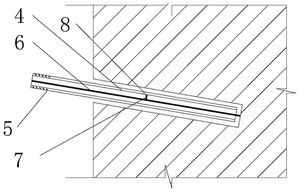
[0046] First, the anchor member used in this method is composed of a hollow anchor rod (in this embodiment, a hollow screw 4 with an inner partition) and a nut 21, and the anchoring section of the hollow screw 4 with an inner partition extends into the anchor matrix In the borehole 2 of 1, the free section of the hollow screw rod 4 with an inner partition is provided with a threaded buckle 5 and is tightly connected with the nut 21.

[0047] The steps of its anchoring method are:

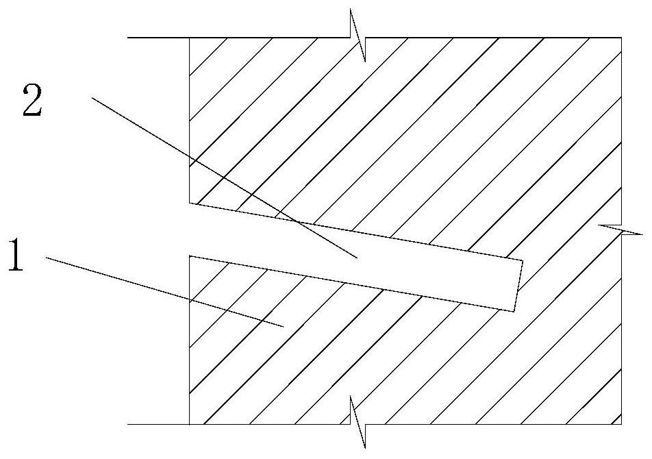
[0048] Step 1, first drill holes on the anchorage substrate 1 such as the wall, such as figure 1 Shown; the diameter of the borehole 2 is 2 to 3mm larger than the hollow screw of the anchoring member, so as to fill the screw.

[0049] The borehole is inclined downward, and the angle with the ...

Embodiment 2

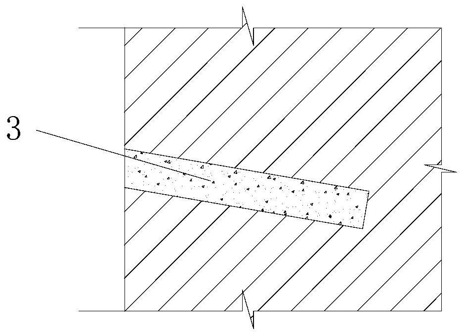
[0077]This embodiment provides a microbial grouting anchorage structure, such as Figure 7 Shown, comprise hollow anchor rod (here is the hollow screw rod 4 of band interior partition), hollow anchor rod has hollow cavity, horizontal inner partition and vertical inner partition are arranged in the hollow cavity of hollow anchor rod The plate, the horizontal inner partition and the vertical inner partition are perpendicular to each other, and the cavity of the hollow anchor rod is divided into four pipes for grouting. The hollow cavity of the hollow anchor rod is provided with a central diaphragm along the radial direction. The partition blocks two of the pipes, the middle of the hollow anchor rod is provided with a side hole connecting the hollow cavity, the hollow screw extends into the borehole 2 of the anchoring matrix 1, and the carbon dioxide induced by microorganisms is placed between the borehole and the hollow screw. Calcium cement body 22, the side wall of the anchori...


PUM


Abstract

The invention discloses a microorganism grouting and anchoring method and structure in which a partition plate is arranged in a cavity to form a pipeline. Two partitions are arranged to cross to divide the hollow cavity into multiple pipes for grouting. A transverse partition is arranged radially in the middle of the hollow cavity to block some of the pipes, and the hollow anchor rod is set on the side connected to the blocked pipe hole; inject the grouting fluid into the drill hole through the pipe; install the fixed object on the side wall of the anchor base, and install the nut on the hollow anchor rod to complete the anchor.

Description

technical field [0001] The invention belongs to the technical field of grouting and anchoring, and in particular relates to a microbial grouting and anchoring method and structure in which a partition plate is arranged in a cavity to form a pipeline. Background technique [0002] The statements herein merely provide background information related to the present invention and do not necessarily constitute prior art. [0003] Anchor bolts are mechanical fasteners consisting of anchor rods, nuts and backing plates. The anchor rod needs to be anchored into the base of the wall to a certain depth, and then the wall insulation or decorative materials are fixed through the nut. The materials used for cementing anchor bolts mainly include cement-based and epoxy resin. Cement-based materials are not effective when the anchoring depth is large due to the volume shrinkage of cement hardening, the material is prone to water, and poor fluidity; epoxy resin materials are easy to age and...

Claims


Application Information

Patent Timeline
Patent Type & Authority Patents(China)
IPC IPC(8): E04B1/38E04B1/76E04F13/08
CPCE04B1/38E04B1/7629E04F13/0801
Inventor 贾强张鑫赵庆瑞盛乾
Owner SHANDONG JIANZHU UNIV
Why Eureka
Try Eureka