Eureka AIR delivers breakthrough ideas for toughest innovation challenges, trusted by R&D personnel around the world.

Continuous cross-shaped water pumping device utilizing water energy

A cross-shaped and water pump technology is applied in the field of new energy equipment, which can solve the problems of small water-lifting amount and low water-lifting efficiency, and achieve the effect of increasing efficiency.

Inactive Publication Date: 2020-11-03
苏州波粒新能源科技有限公司
View PDF1 Cites 0 Cited by
  • Summary
  • Abstract
  • Description
  • Claims
  • Application Information

AI Technical Summary

Problems solved by technology

However, this solution has the following problems: the amount of water to be lifted is small, especially when the water flow is small and the flow is slow, it is difficult to drive the water wheel power unit to run, resulting in low water-lifting efficiency

Method used


Image

  • Continuous cross-shaped water pumping device utilizing water energy
  • Continuous cross-shaped water pumping device utilizing water energy
  • Continuous cross-shaped water pumping device utilizing water energy

Examples


Embodiment Construction

[0025] The present invention will be further elaborated below by means of the accompanying drawings and examples.

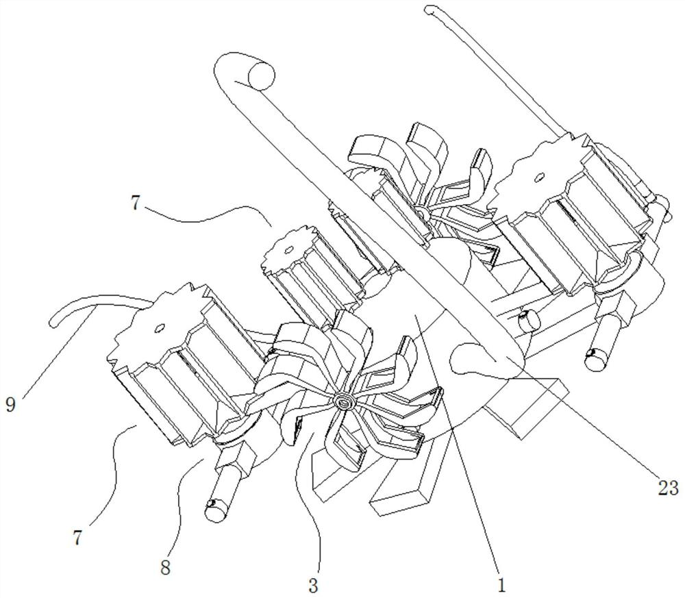
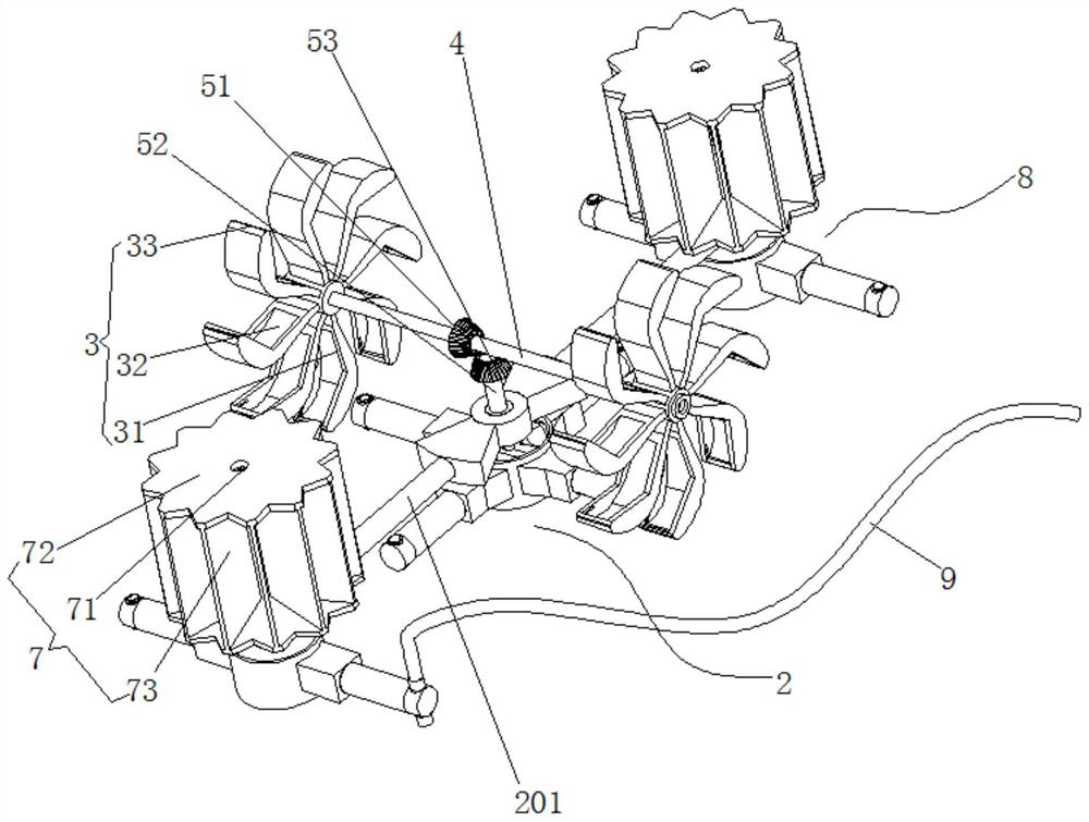
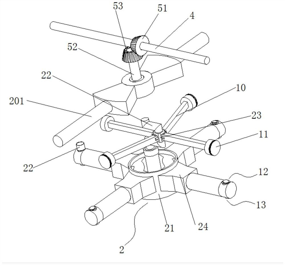
[0026] Such as Figure 1-6 Shown: a continuous cross-shaped water pump using water energy, including a floating body frame 1 located in the middle, a water pumping part 1 and a water energy transmission part 3 arranged on the floating body frame 1, and the floating body frame 1 is horizontally pivoted There is a rotating rod 4, which extends to both sides. The water energy transmission part 3 is arranged at both ends of the rotating rod 4, and the water pumping part is driven by the conductive part 5 to pump water. The two sides of the floating body frame 1 are connected with support rods 2016, A cross shape is formed between the support rod 2016 and the rotating rod 4, and the outer end of the support rod 2016 is connected with the fan blade rotating assembly 7, and the lower side of the fan blade rotating assembly 7 is connected with the second pumping part 8, ...


PUM


Abstract

The invention discloses a continuous cross-shaped water pumping device utilizing water energy. The device comprises a floating body frame located in the middle, a first water pumping piece and water energy transmission pieces, the first water pumping piece and the water energy transmission pieces are arranged on the floating body frame, a rotating rod is horizontally pivoted to the floating body frame, the rotating rod extends towards the two sides, and the water energy transmission pieces are arranged at the two ends of the rotating rod and drive water pumping pieces to pump water through a conduction piece. Supporting rods are connected to the two sides of the floating body frame, and a cross shape is formed between the supporting rods and the rotating rod. According to the water pumpingdevice, the first water pumping piece which is simultaneously matched with the water energy transmission pieces and a fan blade rotating assembly is arranged, water is pumped in a four-pumping-head manner, second water pumping pieces which are symmetrically arranged on the two sides of the first water pumping piece and adopt two pumping heads are arranged, and a first valve and a second valve arematched, so that uninterrupted reciprocating efficient water lifting is realized; and then, a long rope is connected to the floating body frame, the whole water pumping device can change the direction at any time along with the wind direction and is always located on the windward side, wind energy and water energy can be utilized to the maximum extent even when the wind speed is small or water flow is small, and the water pumping efficiency is improved.

Description

technical field [0001] The invention relates to the technical field of new energy equipment, in particular to a continuous cross-shaped water pump utilizing water energy. Background technique [0002] Rural production is an important support for my country's rural economic and social development. Since the 1970s, my country's cultivated land area has continued to decrease, but the irrigated area has generally increased steadily, and the irrigation level has continued to improve, but this is only limited to the developed plains and some areas. Mechanized developed areas. In the southwestern mountainous area and some remote areas, the level of mechanization is relatively backward, and irrigation is still a big problem. For the irrigation of small farmlands and vegetable fields in mountainous areas or plains, most farmers use electric motors, diesel engines, manpower water trucks and other equipment to carry out water pumping and irrigation. Diesel engines pollute the environme...

Claims


Application Information

Patent Timeline
Patent Type & Authority Applications(China)
IPC IPC(8): F04B17/00F04B17/02F03B13/00F03B3/12F03D9/28F03D3/06F03D7/06
CPCF03B3/121F03B13/00F03D3/062F03D7/06F03D9/008F04B17/00F04B17/02F03D9/28Y02E10/20Y02E10/74Y02P80/10Y02A20/00
Inventor 刘涛
Owner 苏州波粒新能源科技有限公司
Why Eureka
Eureka Blog
Learn More