Dielectric filter

A dielectric filter and dielectric resonator technology, applied in the field of communication, can solve the problem of the second harmonic being close to the passband of the filter, and achieve the effects of low manufacturing cost, simple design structure, and high frequency suppression.

Inactive Publication Date: 2020-11-03
WUHAN FINGU ELECTRONICS TECH
View PDF9 Cites 4 Cited by
  • Summary
  • Abstract
  • Description
  • Claims
  • Application Information

AI Technical Summary

Problems solved by technology

[0006] The present invention provides a new filter to solve the problem in the prior art that the second harmonic is relatively close to the passband of the filter caused by the negative coupling of the filter

Method used


Image

  • Dielectric filter
  • Dielectric filter
  • Dielectric filter

Examples


Embodiment Construction

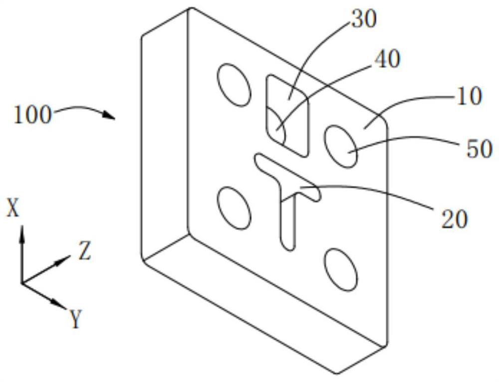
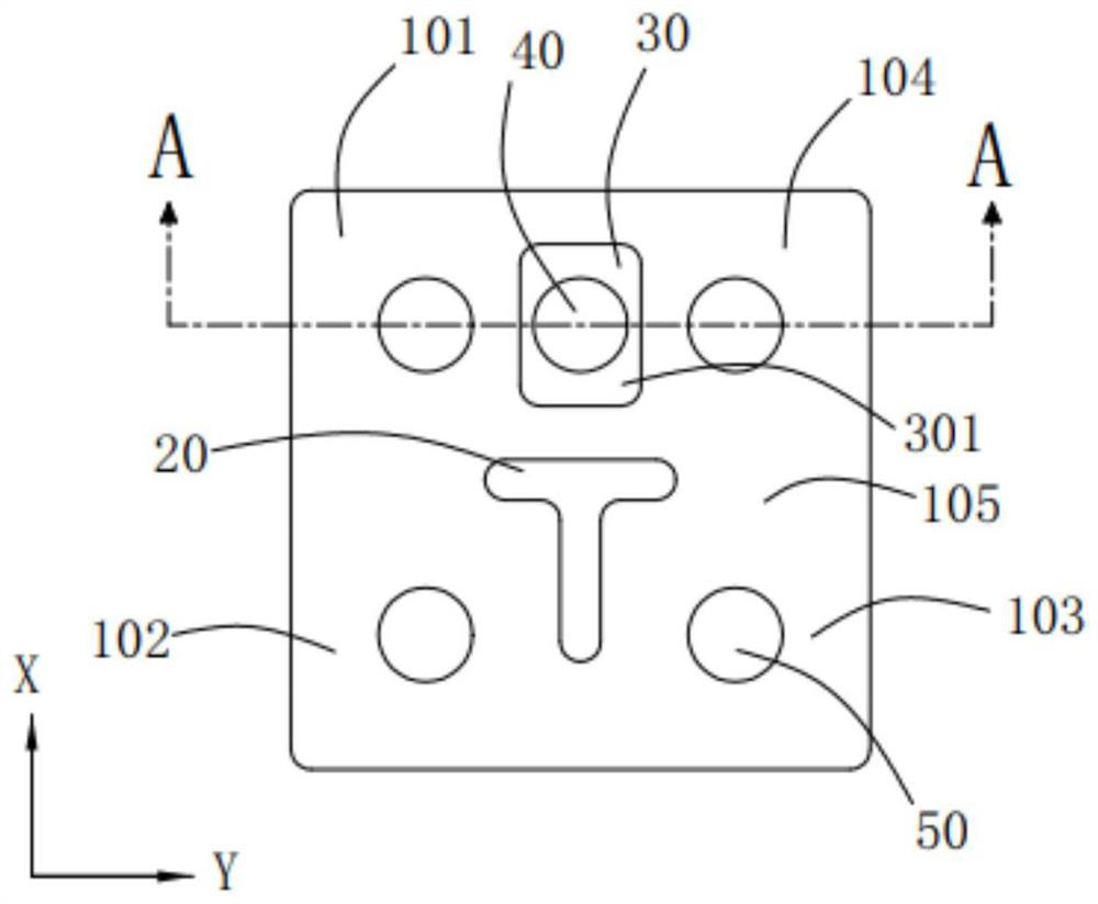
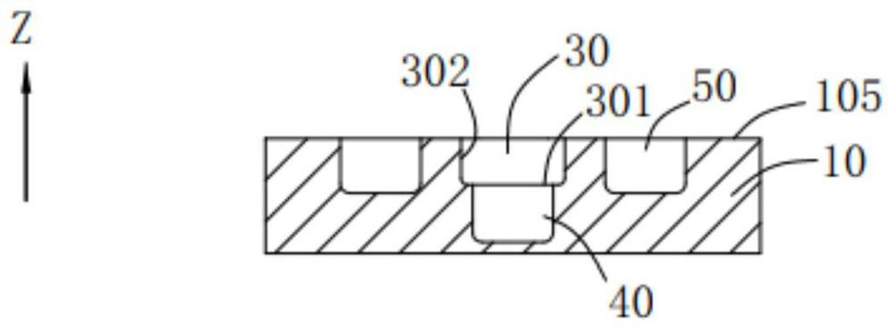
[0023] The technical solutions in the embodiments of the present invention will be clearly and completely described below in conjunction with the accompanying drawings in the embodiments of the present invention. Obviously, the described embodiments are only a part of the embodiments of the present invention, rather than all the embodiments. Based on the embodiments of the present invention, all other embodiments obtained by those of ordinary skill in the art without creative work shall fall within the protection scope of the present invention.

[0024] In the description of the present invention, it should be understood that the terms "center", "upper", "lower", "front", "rear", "left", "right", "vertical", "horizontal", The orientation or positional relationship indicated by "top", "bottom", "inner", "outer", etc. are based on the orientation or positional relationship shown in the drawings, and are only for the convenience of describing the present invention and simplifying the...


PUM


Abstract

The dielectric filter at least comprises two dielectric resonators, and each dielectric resonator comprises a body and a debugging hole; a sunken area is arranged between the two dielectric resonatorsto realize high-frequency suppression, the body is provided with at least one negative coupling hole, the negative coupling hole is arranged in a range corresponding to the sunken area, the cross sectional area of the negative coupling hole is smaller than the area of the sunken area, and the negative coupling hole is a blind hole. The sum of the depths of the blind hole and the recessed area isless than the thickness of the body and larger than the depth of the debugging hole, and the negative coupling hole is used for achieving capacitive coupling between the two dielectric resonators. Bymeans of the design of the recessed area, needed frequency is designed to be insensitive frequency, and unnecessary frequency (namely harmonic waves) is pushed away; the harmonic waves are far away from the normal working frequency (also called high-frequency suppression) of the dielectric filter as far as possible, so the dielectric filter is convenient for pushing away the harmonic waves and isbeneficial to realizing high-frequency suppression.

Description

Technical field [0001] The present invention relates to the field of communication technology, in particular to a dielectric filter. Background technique [0002] Radio frequency filters are commonly used components in communication equipment, and there are many types and forms. The metal coaxial cavity filter is used in the radio frequency front end of high-power wireless communication base stations because of its excellent performance indicators (including insertion loss and power capacity). [0003] With the advent of the "big bang" era of 5G communications, 5G base stations have gradually become popular around the world, and filters are the key components in communication base stations that determine the anti-interference characteristics of base stations. Traditional 4G base stations use aluminum cavity filters to make bulky cavity filters, which cannot be applied on a large scale under the 5G base station Massive MIMO architecture due to defects in size, weight, and cost. Th...

Claims


Application Information

Patent Timeline
Patent Type & Authority Applications(China)
IPC IPC(8): H01P1/20
CPCH01P1/2002
Inventor 刘文朱晖
Owner WUHAN FINGU ELECTRONICS TECH
Why Eureka
Try Eureka