
Power factor correction circuit and control method thereof, medium, compressor and air conditioner

A power factor correction and circuit technology, which is applied in compressors and air conditioners, media, totem pole power factor correction circuits and their control fields, can solve the problems of multi-switching devices, high working efficiency, high cost of use, etc., and achieve low loss , Improve operating efficiency, the effect of high efficiency advantages

Pending Publication Date: 2022-01-25
GD MIDEA AIR-CONDITIONING EQUIP CO LTD +1
View PDF0 Cites 0 Cited by
  • Summary
  • Abstract
  • Description
  • Claims
  • Application Information

AI Technical Summary

Problems solved by technology

Some existing power factor correction circuits have a boost function, that is, the output voltage of the power factor correction circuit is higher than the input voltage, but when it is required to achieve double voltage output, that is, the output voltage is twice the input voltage, the existing power factor The correction circuit needs to use more switching devices, and it is difficult to achieve high working efficiency. Therefore, when there is a need for boosting and voltage doubling in the prior art, a power factor correction circuit and a special voltage doubling circuit need to be equipped.
The high complexity of the circuit will lead to high usage cost and high failure rate

Method used


Image

  • Power factor correction circuit and control method thereof, medium, compressor and air conditioner
  • Power factor correction circuit and control method thereof, medium, compressor and air conditioner
  • Power factor correction circuit and control method thereof, medium, compressor and air conditioner

Examples


Embodiment Construction

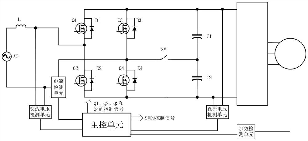
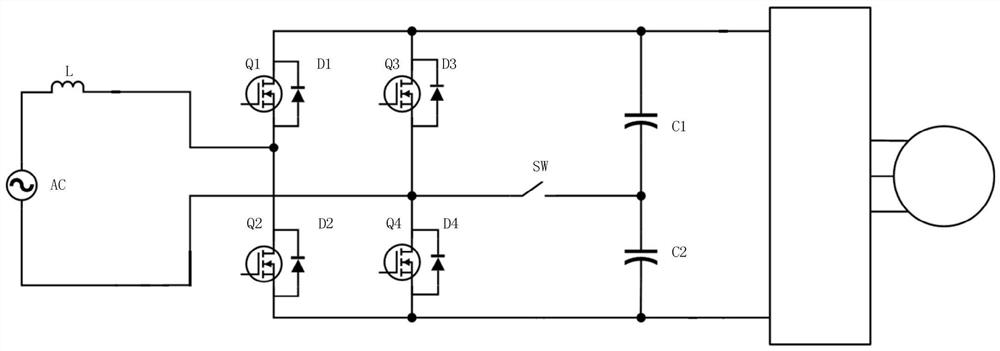
[0137] refer to figure 1 , In an embodiment of the present invention, a totem pole power factor correction circuit is provided, which includes a rectification module, an inductor module, a capacitor module, a switch module and a control module.

[0138] In an embodiment of the present invention, the rectification module includes a plurality of unidirectional conduction units and a plurality of switch units, these unidirectional conduction units are connected in the shape of a bridge, and each unidirectional conduction unit is connected in parallel with a switch unit. In the embodiment of the present invention, a diode can be used as a unidirectional conduction unit, and other devices with unidirectional conduction capability can also be used as a unidirectional conduction unit; triodes, field effect transistors, or insulated gate bipolar transistors, etc. The device that controls the on-off capability is used as a switch unit.

[0139] In the embodiment of the present inventi...


PUM


Abstract

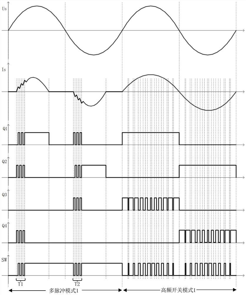
The invention discloses a totem pole power factor correction circuit and a control method thereof, a medium, a compressor and an air conditioner. The totem pole power factor correction circuit comprises a rectifier module, an inductor module, a capacitor module, a switch module and a control module, and the control module is used for controlling the rectifier module and the switch module to work in a high-frequency switch mode or a multi-pulse mode according to working parameters of the load. When working in a high-frequency switching mode, the input current waveform can be controlled to change along with the input voltage, so that the input current harmonic wave and the power factor are improved, the bus voltage is raised, and boost output is realized; and when working in a multi-pulse mode, the totem-pole power factor correction circuit can realize voltage-multiplying output with lower loss, and the totem-pole power factor correction circuit can realize boosting and voltage-multiplying functions, so that the totem-pole power factor correction circuit adapts to voltage requirements of different working parameters of a load, and keeps the advantage of high efficiency of the power factor correction circuit. The correction circuit is widely applied to the technical field of electronic power.

Description

technical field [0001] The invention relates to the technical field of electronic power, in particular to a totem pole power factor correction circuit, a control method thereof, a medium, a compressor and an air conditioner. Background technique [0002] In the existing electronic power technology, in order to obtain a higher power factor, a PFC (Power Factor Correction, power factor correction) circuit is commonly used to provide the bus voltage. Some existing power factor correction circuits have a boost function, that is, the output voltage of the power factor correction circuit is higher than the input voltage, but when it is required to achieve double voltage output, that is, the output voltage is twice the input voltage, the existing power factor The correction circuit needs to use more switching devices, and it is difficult to achieve high working efficiency. Therefore, in the prior art, when there is a demand for boosting and voltage doubling, a power factor correcti...

Claims


Application Information

Patent Timeline
IPC IPC(8): H02M1/42H02M1/12H02M7/219H02P27/06
CPCH02M1/4233H02M1/4225H02M1/12H02M7/219H02P27/06Y02B70/10
Inventor 徐锦清曾贤杰张杰楠文先仕钟雄斌胡斌
Owner GD MIDEA AIR-CONDITIONING EQUIP CO LTD
Learn More