Resonator

A resonator and resonant region technology, applied in the field of resonators, can solve the problems of Q value reduction, dissipation, and composite film discontinuity at the anti-resonance point, and achieve the effect of improving Q value and reducing transverse wave resonance.

Inactive Publication Date: 2020-11-03
AAC TECH NANJING
View PDF0 Cites 2 Cited by
  • Summary
  • Abstract
  • Description
  • Claims
  • Application Information

AI Technical Summary

Problems solved by technology

[0004] However, in the related art, the composite film is discontinuous in the excitation region and outside the excitation region, and when the transverse sound wave propagates outward to the side of the second electrode and the edge of the resonance region, an acoustic wave scattering effect occurs each time, resulting in the generation of a large number of transverse waves. Superimposed resonance, and a large amount of acoustic wave energy enters the substrate to form dissipation, resulting in a significant decrease in the Q value of the anti-resonance point

Method used


Image

  • Resonator
  • Resonator
  • Resonator

Examples


Embodiment approach 1

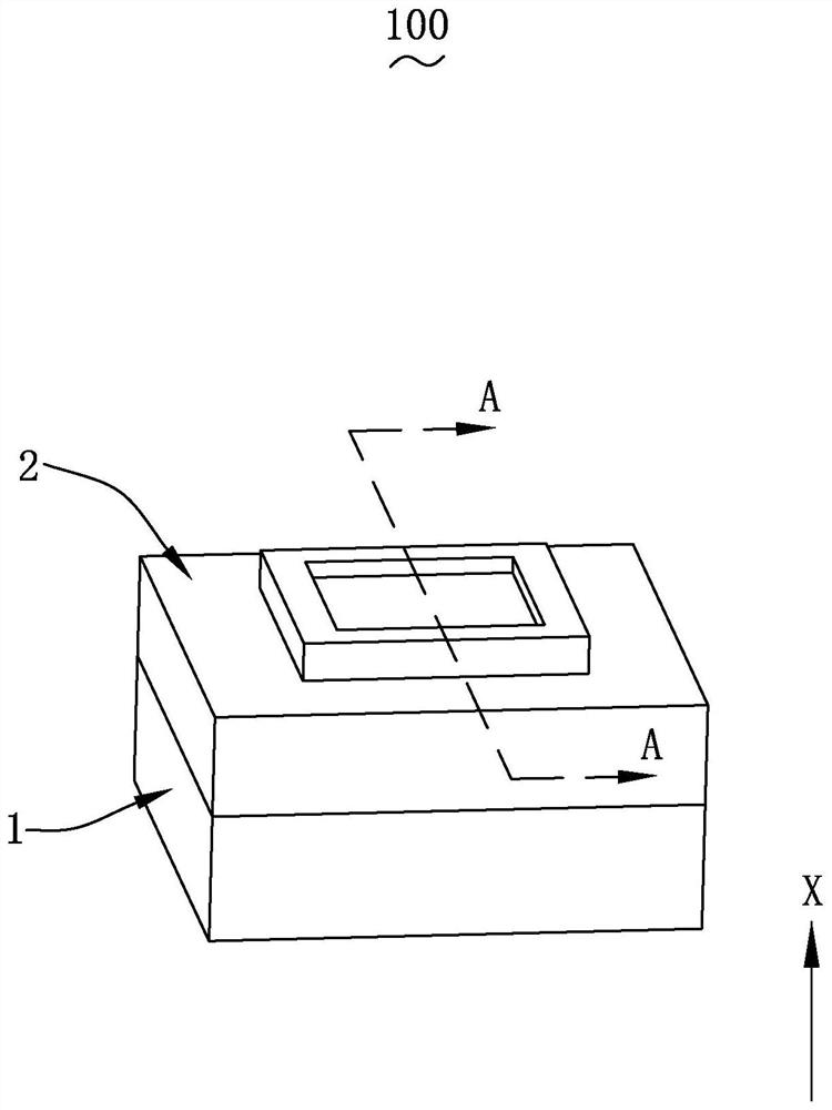
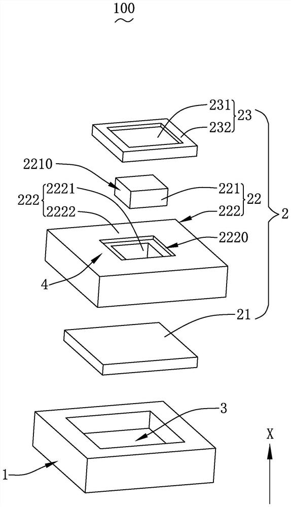
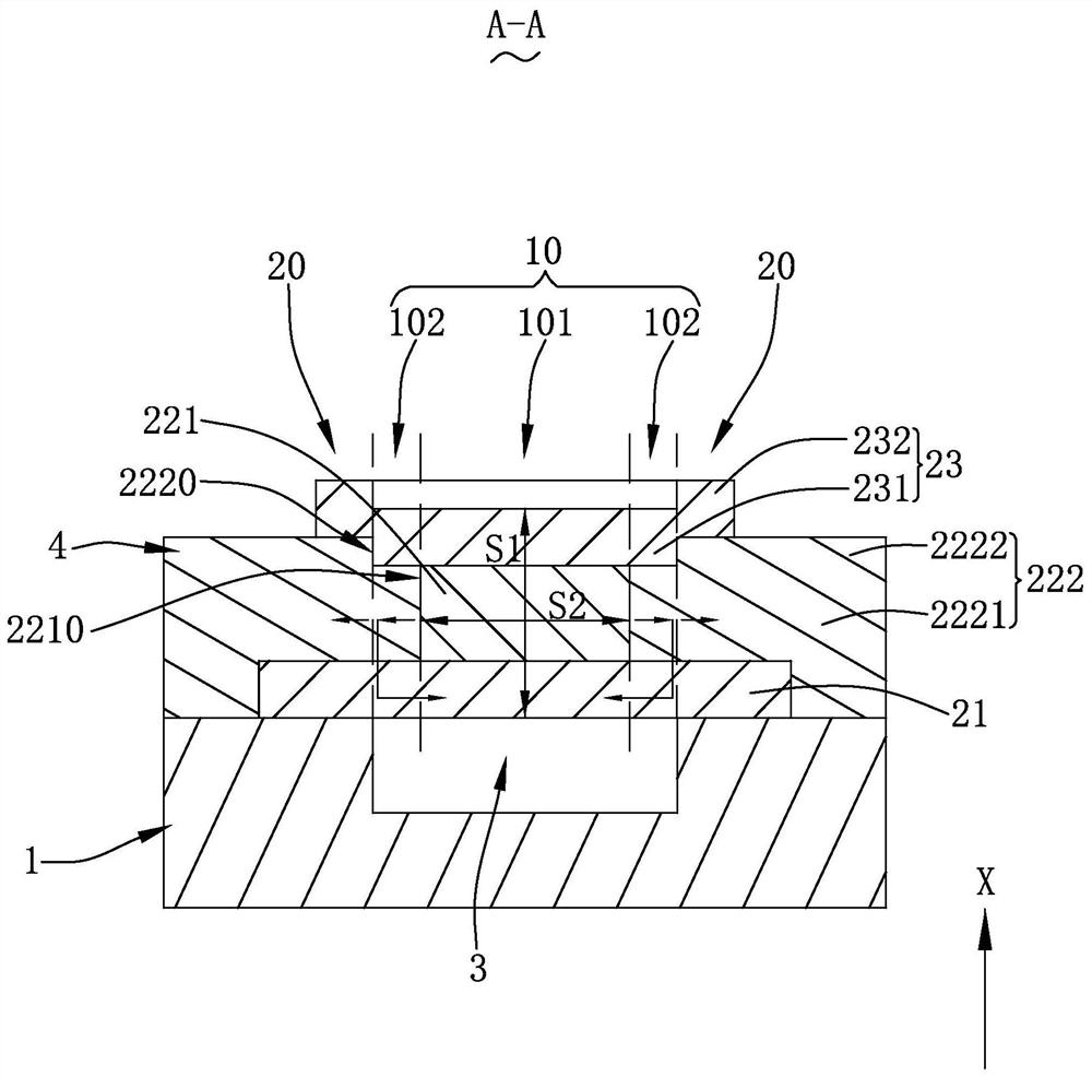
[0028] see Figure 1-3 As shown, the present invention provides a resonator 100, which includes a substrate 1, a composite film 2 arranged above the substrate 1 along a first direction (ie, the X-axis direction), and a composite film 2 arranged between the substrate 1 and the composite film. 2 between the longitudinal acoustic wave reflector 3, wherein the first direction is the thickness direction of the resonator 100.

[0029] The composite film 2 includes a first electrode 21, a piezoelectric functional film 22 and a second electrode 23 arranged in sequence along the first direction, and the first electrode 21 is arranged on the substrate 1 and the longitudinal acoustic wave reflector 3 or more.

[0030] The arrangement of two adjacent structures is not limited. For example, in the first embodiment, the composite film 2 is stacked on the surface of the substrate 1, and the first electrode 21 is stacked on the The base 1 is also covered on the longitudinal acoustic wave re...

Embodiment approach 2

[0047] see Figure 4-5 shows the resonator 100a of Embodiment 2, Figure 4 In essence figure 2 The schematic diagram of another embodiment of the shown structure, the resonator 100a of the second embodiment is a derivative embodiment of the sound-generating device of the first embodiment, the structures of the two are basically the same, and the same parts will not be described one by one, but the embodiment The main differences between the two resonators 100a are:

[0048] The longitudinal acoustic wave reflector 3a is a Bragg acoustic mirror arranged on the side of the substrate 1a close to the first electrode 21a, and the first electrode 21a is arranged on the side of the Bragg acoustic mirror away from the substrate 1a; more specifically, the first electrode 21a is stacked On the surface of the Bragg acoustic reflector far away from the substrate 1a, of course, in other embodiments, it is also feasible that the first electrode and the Bragg acoustic reflector are not di...


PUM


Abstract

The invention provides a resonator, which comprises a substrate, a composite film and a longitudinal sound wave reflector, and is characterized in that the composite film comprises a first electrode,a piezoelectric functional film and a second electrode which are sequentially arranged along a first direction, and the first electrode is arranged on the substrate and the longitudinal sound wave reflector; the piezoelectric functional film comprises a longitudinal piezoelectric film and a longitudinal non-piezoelectric film; the longitudinal non-piezoelectric film comprises a main body part andan annular convex ring extending from the main body part; an area defined by the orthographic projection of the inner side surface of the convex ring to the main body part in the first direction is aresonance area, and an area, outside the resonance area, of the resonator is a non-resonance area; the first electrode and the second electrode completely cover the resonance area, and the part, located in the non-resonance area, of the second electrode is arranged on the convex ring; the acoustic impedances of the resonator in the resonance area and the non-resonance area are different, and the acoustic impedances of the parts, located in the resonance area, of the first electrode, the piezoelectric functional film and the second electrode are approximately unchanged. Compared with the priorart, the energy loss of the resonator is small, and the Q value is increased.

Description

【Technical field】 [0001] The invention relates to the technical field of resonators, in particular to a film bulk acoustic wave resonator. 【Background technique】 [0002] With the increasing number of smart devices and the continuous popularization of Internet of Things and 5G technologies, the demand for high-performance filters and multiplexers is increasing. As an important part of filters and multiplexers, acoustic resonators have been the focus of research in recent years. [0003] In the related art, a resonator includes a substrate stacked along a first direction, a first electrode, a piezoelectric film, and a second electrode, and a longitudinal acoustic wave reflector is arranged between the substrate and the first electrode; the longitudinal acoustic wave The area surrounded by the inner edge of the orthographic projection of the reflector along the first direction is a resonance area, and the area enclosed by the projection of the second electrode along the first...

Claims


Application Information

Patent Timeline
IPC IPC(8): H03H9/17H03H9/02
CPCH03H9/02086H03H9/171
Inventor 窦韶旭吕丽英杨帅吴一雷韩琦吴珂王超
Owner AAC TECH NANJING
Why Eureka
Try Eureka