

Drying equipment used for producing bamboo product
A technology for drying equipment and bamboo products, which is applied in the direction of mechanical equipment, drying solid materials, drying gas arrangement, etc. It can solve the problems of affecting quality and easy cracking, and achieve the effect of improving quality, improving toughness and improving shaping effect
- Summary
- Abstract
- Description
- Claims
- Application Information
AI Technical Summary
Problems solved by technology
Method used
Image

Examples
Embodiment 1
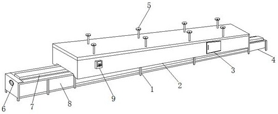
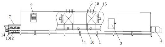
[0024] refer to Figure 1-3 , a kind of drying equipment for the production of bamboo products, comprising a bracket 1, the middle part of the top outer wall of the bracket 1 is fixedly connected with a hot air chamber 2, and the top outer wall of the bracket 1 is located on both sides of the hot air bin 2 and is respectively provided with a discharge tail section 4 And the feed head section 8, the end of the bracket 1 is provided with a feed inlet 6 near the side of the feed head section 8, and the top outer wall of the bracket 1 is provided with a central heating cylinder 7 near the side of the feed head section 8 , There are shaping components 14 symmetrically distributed on both sides between the feed inlet 6 and the central heating cylinder 7, the inner wall of the bracket 1 is located on the side of the hot air chamber 2, and the delivery roller group 11 is provided, and the end outer wall of the delivery roller group 11 A transmission roller is sleeved, and the outer wa...
Embodiment 2
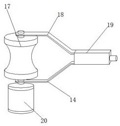
[0027] refer to Figure 4 , a kind of drying equipment for the production of bamboo products. Compared with Embodiment 1, the main difference of this embodiment is that in this embodiment, it also includes eddy current coils 21, and the outer walls of both sides of the shaping roller 17 are provided with heat conduction grooves, and the eddy current coils 21 The outer wall is fixedly connected to the inner wall of the heat conduction groove.
[0028] The working principle of this embodiment: based on the working principle in embodiment 1, the two ends of the shaping roller 17 in the shaping assembly 14 are added with eddy current coils 21, and the shaping roller 17 itself is in a heated state, which can better carry out bamboo Thermal shaping to improve the shaping effect.
PUM
 Abstract
Description
Claims
Application Information