
Radome manufacturing equipment based on glue-printing bonding stretching method

A technology of stretching method and radome, which is applied in the direction of frameless dome cover, radiation unit cover, measuring device, etc., which can solve the problems of disjoint connection, glue sticks can not be evenly distributed honeycomb core, etc.

Inactive Publication Date: 2020-11-06
安徽科易果网络科技有限公司
View PDF0 Cites 0 Cited by
  • Summary
  • Abstract
  • Description
  • Claims
  • Application Information

AI Technical Summary

Problems solved by technology

[0003] Most of the existing transmitting antennas are used in conjunction with the arc-shaped radome, and the raw material of the radome is a honeycomb core, which has the characteristics of light weight. Steps such as glue stretching, stretching and cutting, etc., among which glue stretching is called printing glue bonding stretching method, that is, using the viscosity of the glue stick to stretch, and because the glue stick has a certain fluidity after melting, the flow The final glue sticks cannot be evenly distributed on the surface of the honeycomb core; in addition, the force of the honeycomb core being stretched by glue is not connected with the distance of the cutting knife, so the honeycomb core after cutting cannot show honeycomb shape and use its corresponding function, so a kind of radome production equipment based on printing glue bonding stretching method came into being

Method used


Image

  • Radome manufacturing equipment based on glue-printing bonding stretching method
  • Radome manufacturing equipment based on glue-printing bonding stretching method
  • Radome manufacturing equipment based on glue-printing bonding stretching method

Examples


Embodiment Construction

[0024] The following will clearly and completely describe the technical solutions in the embodiments of the present invention with reference to the accompanying drawings in the embodiments of the present invention. Obviously, the described embodiments are only some, not all, embodiments of the present invention. Based on the embodiments of the present invention, all other embodiments obtained by persons of ordinary skill in the art without making creative efforts belong to the protection scope of the present invention.

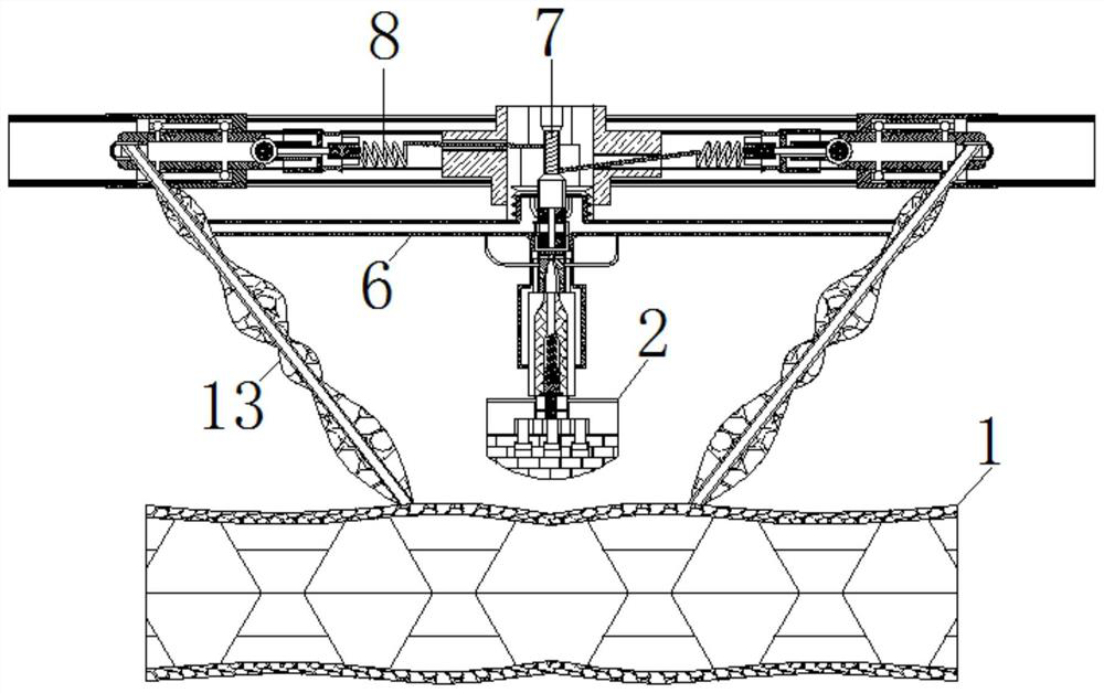
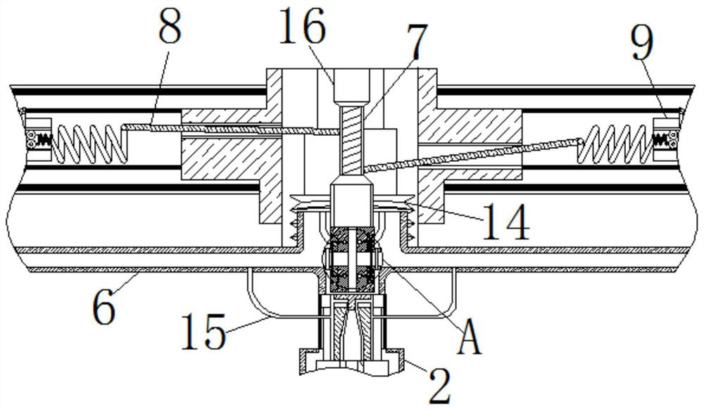
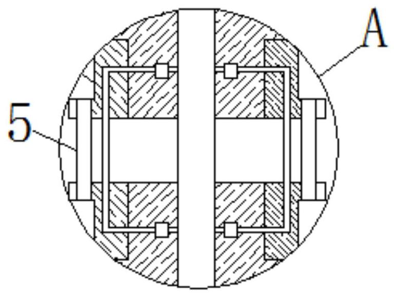
[0025] see Figure 1-7 , a kind of radome manufacturing equipment based on printing glue bonding stretching method, comprising honeycomb core 1, the surface of honeycomb core 1 is movably connected with cutting knife 2, the inside of cutting knife 2 is provided with hollow groove 17, hollow groove 17 The length of the honeycomb core 1 is the same as that of the cutting knife 2; the honeycomb core 1 is a flexible material, and its normal state is a curved shape...


PUM


Abstract

The invention relates to the technical field of manufacturing of radomes for cloud computing, and discloses radome manufacturing equipment based on a glue-printing bonding stretching method. The manufacturing equipment comprises a honeycomb core, the surface of the honeycomb core is movably connected with a cutting knife, the interior of the cutting knife is movably connected with a buffer spring,and the upper end of the buffer spring is movably connected with a liquid flow pipe; a flow dividing plate is movably connected to the upper end of the liquid flow pipe, drainage pipes are movably connected to the two sides of the flow dividing plate, a rotating shaft is movably connected to the top of the flow dividing plate, a pull rope is movably connected to the surface of the rotating shaft,a spring rod is movably connected to the end, away from the rotating shaft, of the pull rope, guide wheels are movably connected to the two sides of the spring rod, and the end, away from the pull rope, of the spring rod is movably connected with a liquid storage plate. Therefore, the cutting knife can be pushed to make contact with the honeycomb core when the rotating shaft moves downwards, dueto the fact that the moving distance of a rubber rod is related to the downward moving distance of the cutting knife, the effect that the cutting distance and the cutting force are related to the stretched degree of the honeycomb core is achieved.

Description

technical field [0001] The invention relates to the technical field of radome production for cloud computing, in particular to a radome production equipment based on a printing glue bonding stretching method. Background technique [0002] Radar means radio detection and ranging, that is, using radio methods to find targets and determine their spatial positions. With the development of technology, radar is gradually used in cloud computing. The combination of the two can help cloud computing better Send and receive related data; where the radar consists of a transmitter, a transmitting antenna, a receiver, a receiving antenna, and so on. [0003] Most of the existing transmitting antennas are used in conjunction with the arc-shaped radome, and the raw material of the radome is a honeycomb core, which has the characteristics of light weight. Steps such as glue stretching, stretching and cutting, etc., among which glue stretching is called printing glue bonding stretching meth...

Claims


Application Information

Patent Timeline
Patent Type & Authority Applications(China)
IPC IPC(8): B29D25/00H01Q1/42G01S7/02
CPCB29D25/00G01S7/02G01S7/027H01Q1/42
Inventor 陈琛
Owner 安徽科易果网络科技有限公司
Learn More