
Magnetized low-temperature cracking device with water-gas separation device

A low-temperature cracking and separation device technology, which is applied to the discharge device, separation method, and separation of dispersed particles of retort gas, and can solve problems affecting the effect of flue gas purification and treatment

Inactive Publication Date: 2020-11-06
鑫源昊(浙江)环保能源科技有限公司 +1
View PDF4 Cites 1 Cited by
  • Summary
  • Abstract
  • Description
  • Claims
  • Application Information

AI Technical Summary

Problems solved by technology

The water is effectively separated, which is the key process, so that the low water content of the flue gas rises to the freezer, alkali washing tank, anoxic combustion, all-oxygen combustion, three-way catalysis, cooling box, activated carbon adsorption, and tail gas treatment system The one-freeze six-step process is completed, the purification treatment is completed, and the discharge is up to standard. The magnetized low-temperature cracking device is specially used to treat organic hazardous waste, and the moisture content of organic hazardous waste is different. Most of the water in organic waste is contained in the flue gas. If the water is not separated, it will seriously affect the purification effect of the flue gas.

Method used


Image

  • Magnetized low-temperature cracking device with water-gas separation device
  • Magnetized low-temperature cracking device with water-gas separation device

Examples


specific Embodiment approach 1

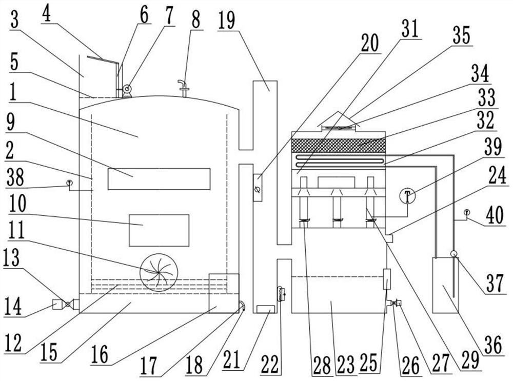
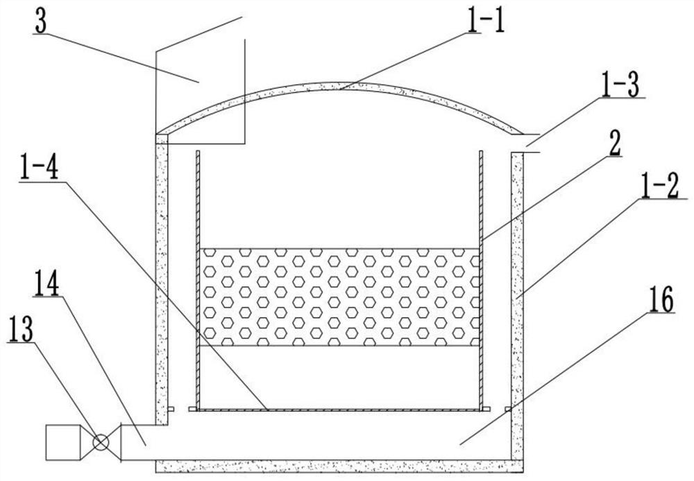
[0022] Combine below Figure 1-2 Description of this embodiment, a magnetized low-temperature pyrolysis device with a water and gas separation device, including a pyrolysis chamber 1, an inner wall of the pyrolysis chamber 2, an explosion-proof valve 8, a surrounding layer containing magnetic ash 9, an observation process port 10, and turbine ash Outlet 11, the inner wall 2 of the cracking chamber is fixedly connected to the inside of the cracking chamber 1, the explosion-proof valve 8 is arranged at the upper end of the cracking chamber 1, and there are multiple surrounding layers 9 containing magnetic ash, and the surrounding layers 9 containing magnetic ash are all fixed. Connected to the cracking chamber 1, the observation process port 10 is set on the cracking cavity 1, and the turbine ash outlet 11 is set on the cracking cavity 1, and it is characterized in that: the cracking cavity 1 includes a vault 1 of the cracking cavity -1, cracking chamber outer wall 1-2, flue gas...

specific Embodiment approach 2

[0025] Combine below Figure 1-2 To illustrate this embodiment, the smoke-free leakage double-door feed transition bin 3, the upper sealing cover plate 4, the bottom sealing cover plate 5, the screw 6 and the drive motor 7, the smoke-free leakage double-door feed transition bin 3 are fixed Connected to the upper end of the cracking chamber 1, the upper sealing cover 4 is rotatably connected to the upper end of the screw 6, the screw 6 is fixedly connected to the output shaft of the driving motor 7, and the bottom sealing cover 5 is fixedly connected to the smoke-free leakage double-door inlet The lower end of the material transition chamber 3, the bottom sealing cover plate 5 is fixedly connected to the upper end of the cracking chamber 1, and the screw rod 6 is rotatably connected to the right end of the smoke-free leakage double-door feed transition chamber 3;

[0026] Turn the upper sealing cover 4, and then start the adjustment motor 7, so that the screw 6 drives the upper...

specific Embodiment approach 3

[0028] Combine below Figure 1-2 Describe the present embodiment, described fire grate 12, sewage outlet valve 13, sewage outlet 14, sewage collecting box 15, magnetized air generating box 16, air inlet pipe 17 and air inlet pipe valve 18, fire grate 12 are fixedly connected in the furnace The lower end of the grate protection plate 1-4, the sewage outlet 14 is fixedly connected to the bottom of the sewage collection box 15, the sewage outlet valve 13 is arranged on the sewage outlet 14, the sewage collection box 15 is fixedly connected to the lower end of the cracking chamber 1, the air inlet pipe 17 is fixedly connected to the magnetized air generating box 16, the air intake pipe 17 is provided with an intake pipe valve 18, the magnetized air generating box 16 is fixedly connected to the lower end of the cracking chamber 1, and the magnetized air generating box 16 is fixedly connected to the sewage collection box 15 on;

[0029]Open the air intake pipe valve 18, the air int...


PUM


Abstract

The invention relates to the technical field of charging equipment, in particular to a magnetized low-temperature cracking device with a water-gas separation device. The device comprises a cracking chamber body, a cracking chamber inner wall, an explosion-proof valve, magnetic ash-containing surrounding layers, an observation process port and a turbine ash residue outlet. The device has the advantages that water vapor in tail gas can be removed; the inner wall of the cracking cavity is fixedly connected to the interior of the cracking cavity; the explosion-proof valve is arranged at the upperend of the cracking cavity; a plurality of magnetic ash-containing surrounding layers are arranged; the plurality of magnetic ash-containing surrounding layers are fixedly connected to the cracking cavity; the observation process port is formed in the cracking cavity; the turbine ash outlet is formed in the cracking cavity; the cracking cavity comprises a cracking cavity arch crown, a cracking cavity outer wall, a flue gas outlet connecting pipe and a fire grate protection plate, the cracking cavity arch crown is fixedly connected to the upper end of the cracking cavity outer wall, the flue gas outlet connecting pipe is fixedly connected to the right end of the cracking cavity outer wall, and the fire grate protection plate is fixedly connected to the lower end of the cracking cavity innerwall.

Description

technical field [0001] The invention relates to the technical field of charging equipment, in particular to a magnetized low-temperature cracking device with a water and gas separation device. Background technique [0002] The invention relates to an organic flue gas produced by a magnetization low-temperature cracking reaction. The organic flue gas contains more water, and the water will affect the purification effect of the flue gas in a tail gas treatment system. The water is effectively separated, which is the key process, so that the low water content of the flue gas rises to the freezer, alkali washing water tank, anoxic combustion, all-oxygen combustion, three-way catalysis, cooling box, activated carbon adsorption, and tail gas treatment system The one-freeze six-step process is completed, the purification treatment is completed, and the discharge is up to standard. The magnetized low-temperature cracking device is specially used to treat organic hazardous waste, and...

Claims


Application Information

Patent Timeline
IPC IPC(8): C10B53/00C10B27/00F23G7/06B01D53/78B01D53/40B01D53/00
CPCB01D53/002B01D53/04B01D53/40B01D53/78B01D2253/102C10B27/00C10B53/00F23G7/06F23G2209/14
Inventor 承晓平
Owner 鑫源昊(浙江)环保能源科技有限公司
Features
  • Generate Ideas
  • Intellectual Property
  • Life Sciences
  • Materials
  • Tech Scout
  • Unparalleled Data Quality
  • Higher Quality Content
  • 60% Fewer Hallucinations
Learn More