Visual inspection method, device and system based on point cloud data

A technology for visual inspection and point cloud data, applied in image data processing, image data processing, instruments, etc., can solve problems such as environmental interference, low detection efficiency, and inability to meet various detection needs, so as to reduce interference and improve accuracy. Effect

Pending Publication Date: 2020-11-06
武汉闻道复兴智能科技有限责任公司
View PDF0 Cites 10 Cited by
  • Summary
  • Abstract
  • Description
  • Claims
  • Application Information

AI Technical Summary

Problems solved by technology

[0005] In view of the above defects or improvement needs of the prior art, the present invention solves the problems in the existing automatic detection technology

Method used


Image

  • Visual inspection method, device and system based on point cloud data
  • Visual inspection method, device and system based on point cloud data
  • Visual inspection method, device and system based on point cloud data

Examples


Embodiment 1

[0044] In the field of automatic detection, the three-dimensional point coordinate data set of the appearance surface of the object obtained by the measuring instrument is called the point cloud of the object. For a target object with clear geometric features, the spatial geometric features such as spatial contour information, spatial orientation information, and spatial displacement information of the target object can be obtained through the 3D reconstruction technology of point cloud data, and the spatial geometry such as the shape and pose of the target object can be restored. Information, spatial displacement information such as the trajectory of the object can also be obtained through the point cloud data at different time points.

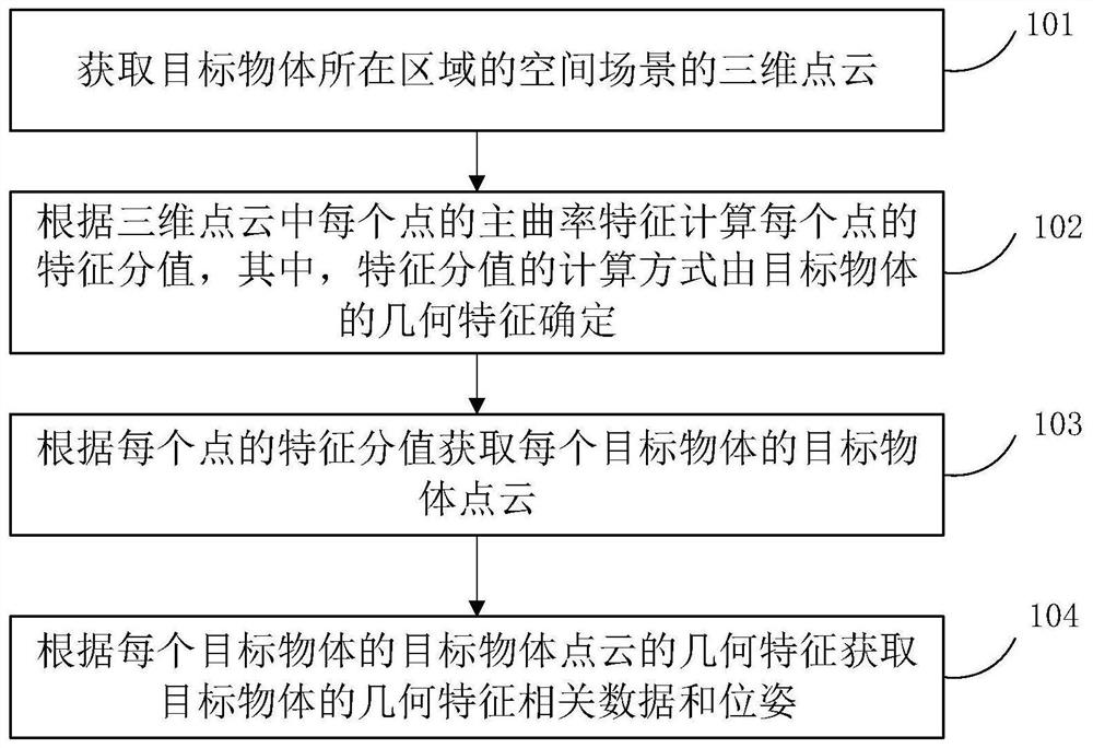
[0045] Such as figure 1 As shown, the specific steps of the method for visual detection based on point cloud data provided by the embodiment of the present invention are as follows:

[0046] Step 101: Obtain a 3D point cloud of a space scene...

Embodiment 2

[0144] On the basis of the method for visual detection based on point cloud data provided in the above-mentioned embodiment 1, the present invention also provides a device for visual detection based on point cloud data that can be used to implement the above method, such as Figure 12 Shown is a schematic diagram of the device architecture of the embodiment of the present invention. The device for visual detection based on point cloud data of this embodiment includes one or more processors 21 and memory 22. Wherein, one processor 21 is taken as an example in FIG. 12 .

[0145] Processor 21 and memory 22 can be connected by bus or other means, Figure 12 The connection via bus is used as an example.

[0146] Memory 22, as a non-volatile computer-readable storage medium of a visual detection method based on point cloud data, can be used to store non-volatile software programs, non-volatile computer-executable programs and modules, such as the embodiment 1 based on Visual insp...

Embodiment 3

[0151] On the basis of the method for visual detection based on point cloud data provided in the above-mentioned embodiment 1 and the device for visual detection based on point cloud data provided in embodiment 2, the present invention also provides a point-based A system for visual inspection of cloud data, such as Figure 13 As shown, it is a schematic structural diagram of the system structure of the visual inspection based on point cloud data provided by the embodiment of the present invention.

[0152] The system based on the visual detection of point cloud data comprises the visual detection device 1 that the visual detection device design based on point cloud data that proposes according to embodiment 2 obtains, also includes robot 2 and at least one visual sensing device 3;

[0153] The visual detection device 1 is connected to the robot 2 through a data interface, and the visual detection device 1 sends the geometric feature-related data and pose of the target object ...


PUM


Abstract

The invention relates to the field of automatic detection, in particular to a visual detection method, device and system based on point cloud data. The method mainly comprises the steps of obtaining three-dimensional point cloud of a space scene of an area where a target object is located; calculating a feature score of each point according to the principal curvature feature of each point in the three-dimensional point cloud, the calculation mode of the feature score being determined by the geometrical feature of the target object; obtaining a target object point cloud of each target object according to the feature score of each point; and obtaining geometrical characteristic related data and poses of the target object according to the geometrical characteristics of the point cloud of thetarget object. According to the invention, various detection requirements of the target object can be realized in a contactless and efficient manner, the interference of the environment on the detection result is reduced, and the detection accuracy is improved.

Description

【Technical field】 [0001] The invention relates to the field of automatic detection, in particular to a method, device and system for visual detection based on point cloud data. 【Background technique】 [0002] With the improvement of the degree of automation in the industrial field, various automation equipment have been used in different operation links, which greatly reduces the amount of manual work and improves the operation efficiency. In order to improve the overall operating efficiency of automation equipment, one of the keys is to complete the automatic detection of various complex tasks in the automation operation, mainly including the spatial contour information, spatial orientation information and spatial displacement information of the target object. [0003] However, existing automatic inspection techniques are generally limited to a single inspection mode, such as sensor inspection or image-based vision inspection. The use of sensors for detection usually requi...

Claims


Application Information

Patent Timeline
IPC IPC(8): G06T7/73G06T7/60G06T7/66G06T7/68G06T1/00
CPCG06T1/0014G06T7/60G06T2207/10028G06T2207/30164G06T7/66G06T7/68G06T7/73
Inventor 胡忠民
Owner 武汉闻道复兴智能科技有限责任公司
Why Eureka
Try Eureka