Air floatation motion platform

A motion table and air flotation technology, applied in the direction of electrical components, magnetic attraction or thrust holding devices, etc., can solve the problems of high processing precision, self-excited oscillation, unfavorable engineering realization, etc., and achieve improved air flotation stiffness and dynamic performance Good, the effect of improving accuracy

Pending Publication Date: 2020-11-06
FUDAN UNIV
View PDF2 Cites 5 Cited by
  • Summary
  • Abstract
  • Description
  • Claims
  • Application Information

AI Technical Summary

Problems solved by technology

However, the air-floating guide rail adopts a highly closed rigid structure, which requires high machining accuracy, weak air-floating rigidity adjustability, and difficult assembly and adjustment. The processing accuracy requirements are strict, and the assembly and adjustment are extremely difficult, so it is not conducive to the engineering realization of the invention
[0004] The air flotation guide rail p

Method used


Image

  • Air floatation motion platform
  • Air floatation motion platform
  • Air floatation motion platform

Examples


Example Embodiment

[0056] In order to make the objectives, technical solutions, and advantages of the embodiments of the present invention clearer, the following describes the embodiments of the present invention in detail with reference to the accompanying drawings. However, a person of ordinary skill in the art can understand that, in each embodiment of the present invention, many technical details are proposed for the reader to better understand the present application. However, even without these technical details and various changes and modifications based on the following embodiments, the technical solution claimed by this application can be realized.

[0057] In the following description, for the purpose of illustrating various disclosed embodiments, certain specific details are set forth to provide a thorough understanding of various disclosed embodiments. However, those skilled in the relevant art will recognize that the embodiments may be practiced without one or more of these specific de...


PUM


Abstract

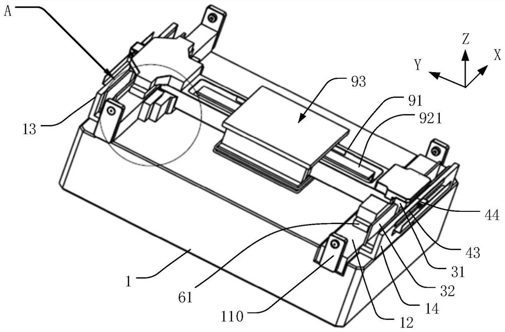
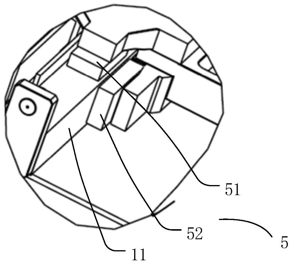
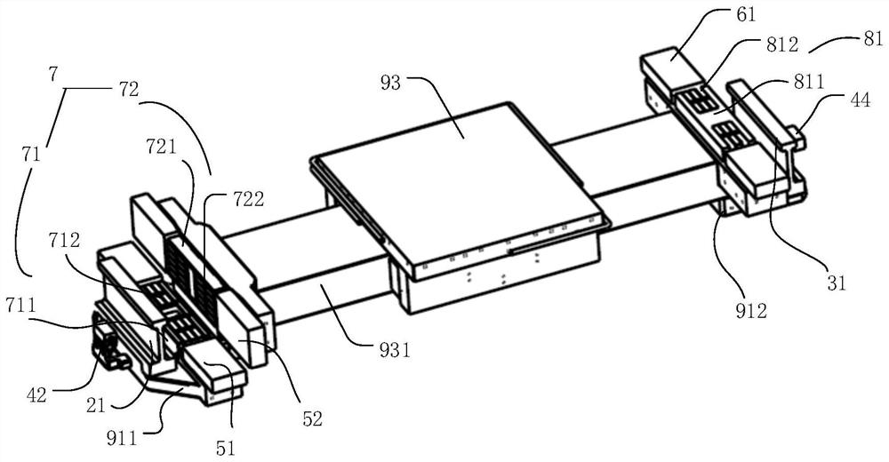
The invention discloses an air floatation motion platform. The air floatation motion platform comprises a base; a first linear motor, which is arranged on the base; a second linear motor, which is arranged on the base, is opposite to the first linear motor, and is separated from the first linear motor; a moving device, which is arranged between the first linear motor and the second linear motor and is connected with a rotor of the first linear motor and a rotor of the second linear motor; a first guide rail, which extends in the length direction of a stator of the first linear motor; a first air floatation device, which forms air floatation between the first air floatation device and the first guide rail; a second guide rail, which extends in the length direction of a stator of the secondlinear motor; a second air floatation device, which forms air floatation between the second air floatation device and the second guide rail; a first magnetic levitation assembly, which forms a magnetic preload between the first magnetic levitation assembly and the first guide rail; and a second magnetic levitation assembly, which forms a magnetic preload between the second magnetic levitation assembly and the second guide rail. Compared with the prior art, the air floatation rigidity is improved, the dynamic performance is good, the requirement for installation and adjustment is low, the structure is compact, and engineering implementation can be achieved.

Description

technical field [0001] The embodiments of the present invention relate to the technical field of semiconductors, and in particular to an air-floating exercise table. Background technique [0002] With the gradual reduction of chip feature size, high-end semiconductor manufacturing equipment has entered the sub-micron or even nanometer level. In addition to the high-yield requirements in manufacturing, the positioning accuracy and operating speed requirements of related equipment are getting higher and higher. More specifically, high-end semiconductor manufacturing equipment has increasingly strict requirements on the positioning accuracy, running speed and stability of linear motion and multi-dimensional motion platforms, such as high-end CNC workbenches, lithography machines, etc. In the field of high-end semiconductor manufacturing, most of the linear guides and motion platforms have adopted air flotation devices. The air flotation guides have no mechanical contact, no fri...

Claims


Application Information

Patent Timeline
IPC IPC(8): H02N15/00
CPCH02N15/00
Inventor 杨晓峰王攀吴立伟刘维珂张佩瑾
Owner FUDAN UNIV
Why Eureka
Try Eureka