Vacuum die-casting die and method for amorphous alloy flexible gear of harmonic reducer
What is Al technical title?
Al technical title is built by PatSnap Al team. It summarizes the technical point description of the patent document.
A harmonic reducer and amorphous alloy technology, applied in the field of vacuum die-casting molds, can solve the problems that the quality and performance of the flexible wheel cannot be guaranteed, the welding seam area is prone to crystallization, and the material utilization rate is low, so as to improve the material utilization rate. And comprehensive mechanical properties, shorten the production cycle, high elasticity effect
Pending Publication Date: 2020-11-10
SONGSHAN LAKE MATERIALS LAB +1
View PDF8 Cites 5 Cited by
Summary
Abstract
Description
Claims
Application Information
AI Technical Summary
This helps you quickly interpret patents by identifying the three key elements:
Problems solved by technology
Method used
Benefits of technology
Problems solved by technology
This method uses the diffusion welding method to connect the flexspline ring gear and the bottom part of the cup, the process is complicated, and the welding seam area is prone to crystallization, which cannot guarantee the quality and performance of the flexspline
[0006] For this reason, there is an urgent need to develop a vacuum die-casting method and mold for the amorphous alloy flexwheel of the harmonic reducer, which can effectively ensure that the amorphous alloy material will not be easily oxidized or crystallized during the die-casting process, thereby improving the flexibility of the flexwheel. Excellent die-casting quality, and overcome the problem of low material utilization rate when traditional machining methods are used to manufacture flexsplines, improve material utilization, and reduce the cost of traditional manufacturing methods for manufacturing flexsplines
Method used
Image
Click on the blue label to locate the original text in one second.
Reading with bidirectional positioning of images and text.
Examples
Embodiment
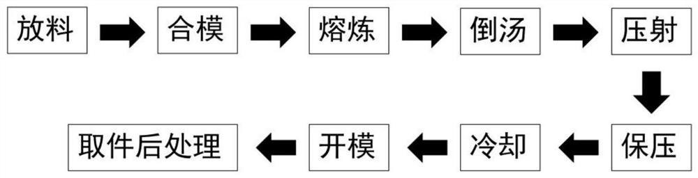
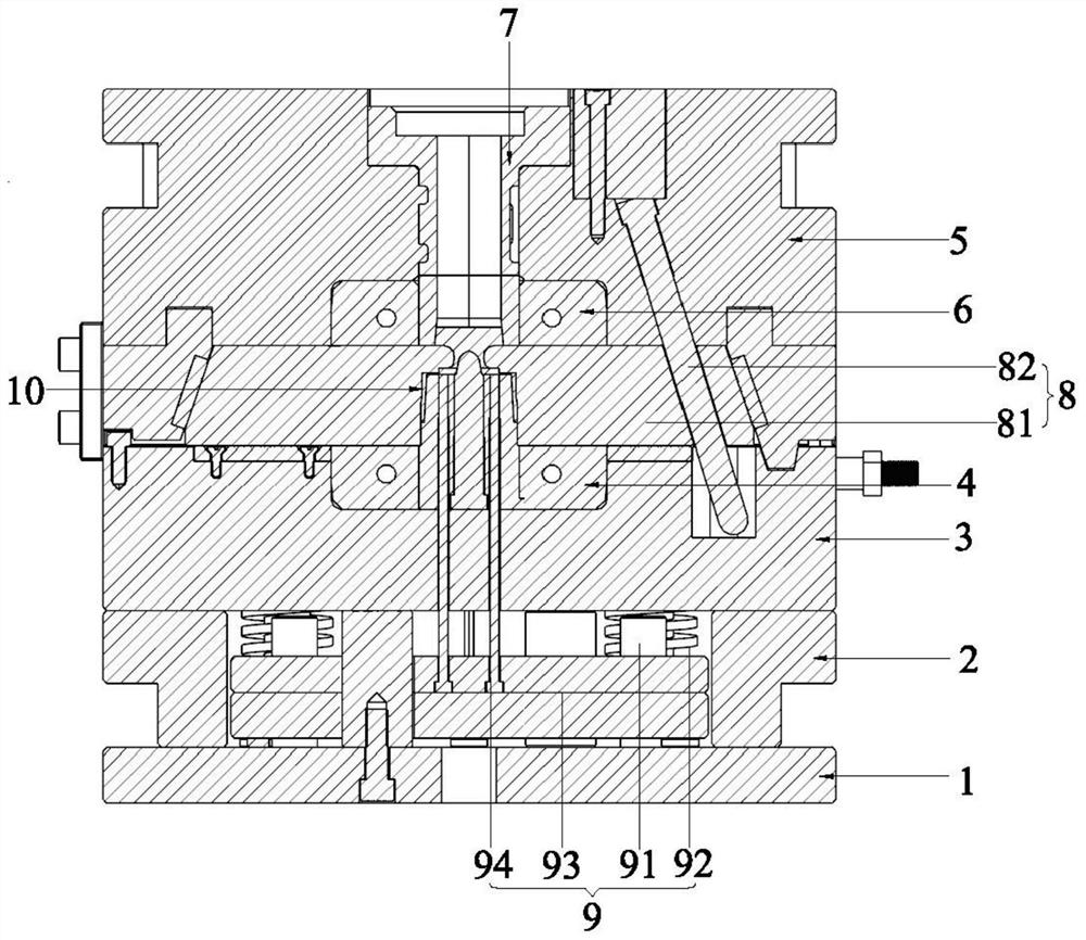
[0029] Example: see figure 1 and figure 2 , a vacuum die-casting method for an amorphous alloy flexible wheel of a harmonic reducer provided in this embodiment, which includes the following steps:
[0030](1) Prepare the amorphous alloy flexible wheel mold: the amorphous alloy flexible wheel mold includes a vacuum box (not shown in the figure) and a bottom plate 1, a square iron 2, a male template 3, and a male mold arranged in the vacuum box. core 4, female template 5, female mold core 6, sprue sleeve 7, core pulling assembly 8 and ejection mechanism 9, the male template 3 is set on the bottom plate 1 through square iron 2, and the male mold core 4 is set on On the male template 3, the position of the female mold core 6 corresponding to the male mold core 4 is set on the female template 5, and the position of the core pulling assembly 8 corresponding to the female mold core 6 is set on the male template 3, and the male mold core 6 is arranged on the male template 3. After ...
PUM
Abstract
The invention discloses a vacuum die-casting die and method for an amorphous alloy flexible gear of a harmonic reducer. The vacuum die-casting die comprises a vacuum box, a bottom plate, square iron,a male die plate, a male die core, a female die plate, a female die core, a sprue bush, a core-pulling assembly and an ejection mechanism, wherein the bottom plate, the square iron, the male die plate, the male die core, the female die plate, the female die core, the sprue bush, the core-pulling assembly and the ejection mechanism are arranged in the vacuum box body. The vacuum die-casting methodis simple in step and easy to achieve; an amorphous alloy material of a Zr-based system is reasonably selected for die casting, fluidity is good, the pouring temperature is low, and the forming capacity is high; and the whole die is placed in a vacuum environment in a matched manner, and it is effectively guaranteed that the amorphous alloy material cannot be easily oxidized or crystallized in thedie casting process. The vacuum die-casting die is reasonable in structure, the manufactured flexible gear has better surface smoothness and dimensional precision, only a small number of post-processing procedures are needed in the subsequent process, the production period is greatly shortened, the machining cost is reduced, in addition, the yield strength and fatigue strength are higher, and theservice life is long.
Description
technical field [0001] The invention relates to the technical field of manufacturing amorphous alloy flexible splines, in particular to a vacuum die-casting mold for an amorphous alloy flexible spline for a harmonic reducer and a method thereof. Background technique [0002] The harmonic reducer consists of three basic parts: flexible spline, rigid spline and wave generator. The flexspline is the core component of the harmonic reducer, and it is a key part for power transmission in the harmonic reducer. Its inner ring matches the outer ring of the flexible bearing and is generally installed at the output end of the reducer. The service process is subjected to complex alternating stress and friction and wear, and is prone to fatigue fracture and wear damage, so its performance is very high. It must be allowed to process the material into a very thin wall to deflect under reasonable stress. Commonly used alloy steels are complicated to process and have a low service life when...
Claims
Application Information
Patent Timeline
Application Date:The date an application was filed.
Publication Date:The date a patent or application was officially published.
First Publication Date:The earliest publication date of a patent with the same application number.
Issue Date:Publication date of the patent grant document.
PCT Entry Date:The Entry date of PCT National Phase.
Estimated Expiry Date:The statutory expiry date of a patent right according to the Patent Law, and it is the longest term of protection that the patent right can achieve without the termination of the patent right due to other reasons(Term extension factor has been taken into account ).
Invalid Date:Actual expiry date is based on effective date or publication date of legal transaction data of invalid patent.