Method for simulating gas-liquid two-phase seepage characteristics in shale natural fractures

A technology of natural fractures and medium gas, which is applied in earth-moving drilling, special data processing applications, wellbore/well components, etc. Control problems such as low accuracy to achieve the effect of saving experimental material funds, saving experimental time, and improving recognition accuracy

Active Publication Date: 2020-11-10
SOUTHWEST PETROLEUM UNIV
View PDF8 Cites 2 Cited by
  • Summary
  • Abstract
  • Description
  • Claims
  • Application Information

AI Technical Summary

Problems solved by technology

Since the width of natural fractures in the reservoir is concentrated in the range of 0.1mm-36mm, there are certain difficulties and observation errors in simulating the gas-liquid flow characteristics in such micro-scale channels through laboratory experiments. The fracturing fluid used in the field is a non-Newtonian fluid and the experiment There are also large differences in laboratory Newtonian fluid simulations, and the difficulty in making experimental models, poor experimental repeatability, and low accuracy of experimental condition control seriously restrict the understanding of gas-liquid two-phase flow characteristics in natural shale fractures.
With the gradual maturity of computer hardware and computational fluid dynamics theory, the use of computational fluid dynamics (CFD) simulation technology to study gas-liquid flow in micro-scale channels has become a reliable means, but the existing general-purpose CFD software is a closed business Software, there are limitations in the transplantation of algorithms and self-modification of formulas

Method used


Image

  • Method for simulating gas-liquid two-phase seepage characteristics in shale natural fractures
  • Method for simulating gas-liquid two-phase seepage characteristics in shale natural fractures
  • Method for simulating gas-liquid two-phase seepage characteristics in shale natural fractures

Examples


Embodiment 1

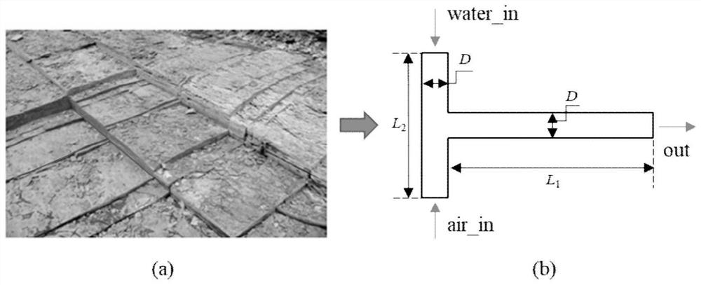
[0043] Step 1. Based on the ANSYS DesignModeler module, establish a T-shaped pipe model. The vertical pipe of the T-shaped pipe model is the gas-liquid two-phase outlet, the upper end of the vertical pipe is the liquid phase inlet, the lower end is the gas phase inlet, and the horizontal pipe is the two-phase outflow.

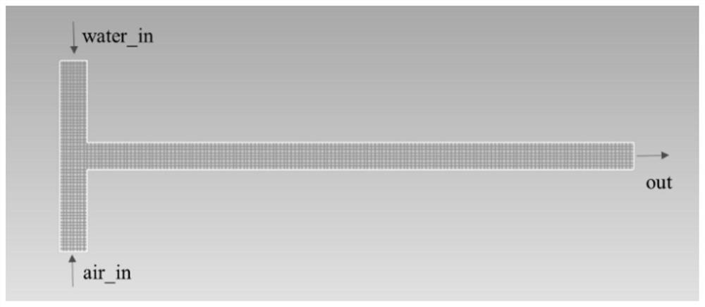
[0044] Create a three-dimensional T-shaped pipe model in the ANSYS DesignModeler module. The upper part of the vertical pipe of the T-shaped pipe is the liquid phase inlet, the lower part is the gas phase inlet, the horizontal pipe is the gas-liquid two-phase outlet, and the outlet pressure is set to 0MPa (the outlet pressure setting can be adjusted according to the needs, this embodiment only gives a setting possibility sex, the model is attached figure 1 shown). The positions of the gas-liquid two-phase inlet and outlet can be adjusted according to actual needs, and are not limited to the above expressions, which are just an inlet and outlet method given in ...


PUM


Abstract

The invention discloses a method for simulating gas-liquid two-phase seepage characteristics in shale natural fractures. The method comprises the following steps of step 1, establishing a T-shaped pipe model in which one end of a vertical pipe is a liquid-phase inlet, the other end of the vertical pipe is a gas-phase inlet, and a transverse pipe is a two-phase flow outlet; step 2, performing griddividing on the T-shaped pipe model established in the step 1 into hexahedral structure grids; step 3, establishing a continuous equation, a phase equation and a momentum equation of a gas-liquid two-phase flow volume flow VOF model, and performing solving by utilizing an interFoam solver in OpenFoam; and step 4, calling the T-shaped pipe grid model in the step 2, and performing iterative computation on the equation solved in the step 3 through time steps to obtain the gas-liquid flow characteristic change in as whole T-shaped pipe. Compared with an indoor experiment, the experiment time, experiment materials and funds can be saved, and the recognition precision is improved. Compared with the application of commercial computational fluid mechanics software, the method disclosed by the invention has the advantages that a bottom-layer algorithm can be transplanted and a formula needs to be modified, and the applicability of various working conditions is improved.

Description

technical field [0001] The invention relates to the technical field of coal-measure gas exploitation, in particular to a method for simulating gas-liquid two-phase seepage characteristics in shale natural fractures. Background technique [0002] Natural fractures are widely developed in shale reservoirs, and natural fractures are the main channels for gas to flow from matrix to fractured fractures. After hydraulic fracturing, the natural fractures of the reservoir contain a large amount of retained fracturing fluid, and the presence of fracturing fluid has a significant impact on the flow characteristics of shale gas desorption. Since the width of natural fractures in the reservoir is concentrated in the range of 0.1mm-36mm, there are certain difficulties and observation errors in simulating the gas-liquid flow characteristics in such micro-scale channels through laboratory experiments. The fracturing fluid used in the field is a non-Newtonian fluid and the experiment There...

Claims


Application Information

Patent Timeline
Patent Type & Authority Applications(China)
IPC IPC(8): E21B49/00G06F30/20
CPCE21B49/00G06F30/20
Inventor 张烈辉黄鑫吴婷婷袁山张博宁张芮菡张墨
Owner SOUTHWEST PETROLEUM UNIV
Why Eureka
Try Eureka