
Damping base facilitating electrical test

A shock-absorbing base, electrical test technology, applied in the direction of spring/shock absorber, spring/shock absorber design features, springs, etc., can solve problems such as affecting the use of electrical equipment, affecting the practical life of equipment, and poor shock absorption effect , to achieve the effect of protecting the service life, reasonable structure design and avoiding resonance

Inactive Publication Date: 2020-11-10
MINJIANG UNIV
View PDF10 Cites 8 Cited by
  • Summary
  • Abstract
  • Description
  • Claims
  • Application Information

AI Technical Summary

Problems solved by technology

[0003] At present, in the electrical test process, many electrical equipment (such as generators, etc.) will generate large vibrations during use, resulting in resonance between several electrical equipment and the base, etc., which will generate greater noise and affect The useful life of the equipment
The existing traditional shock absorption is to fix shock absorbing components such as shock absorbing partitions at the bottom of the electrical equipment. Although the structure is relatively simple, the shock absorbing effect is not good, which affects the use of electrical equipment. Therefore, it is necessary to design A shock-absorbing base for electrical tests can solve this problem

Method used


Image

  • Damping base facilitating electrical test
  • Damping base facilitating electrical test
  • Damping base facilitating electrical test

Examples


Embodiment Construction

[0023] The present invention will be described in further detail below in conjunction with the accompanying drawings and specific embodiments.

[0024] In describing the present invention, it should be understood that the terms "longitudinal", "transverse", "upper", "lower", "front", "rear", "left", "right", "vertical", The orientations or positional relationships indicated by "horizontal", "top", "bottom", "inner", "outer", etc. are based on the orientation or positional relationships shown in the drawings, and are only for the convenience of describing the present invention, rather than indicating or It should not be construed as limiting the invention by implying that a referenced device or element must have a particular orientation, be constructed, and operate in a particular orientation.

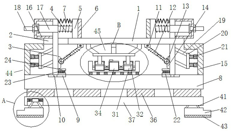
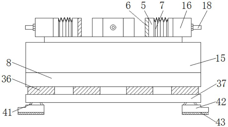
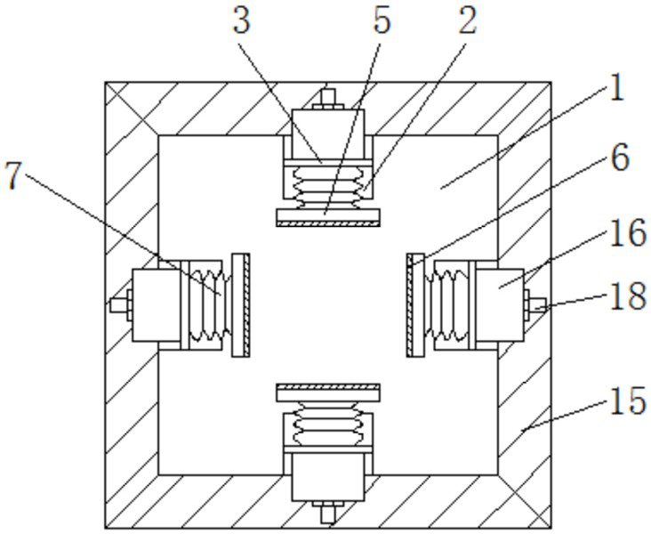
[0025] like Figure 1~5 Shown, the present invention is a kind of shock-absorbing base that is convenient for electric test, comprises rectangular box-shaped support base 44 and is loc...


PUM


Abstract

The invention relates to a damping base facilitating an electrical test. The damping base comprises a supporting base and a liftable horizontal supporting plate, horizontal sliding grooves extending towards the axis of the horizontal supporting plate are formed in the middles of the periphery of the horizontal supporting plate, and vertical supporting plates in sliding fit with the horizontal sliding grooves are arranged in the horizontal sliding grooves in a penetrating manner. First rubber plates located above the horizontal supporting plate are arranged at the inner sides of the vertical supporting plates in parallel, and first springs are connected between the first rubber plates and the vertical supporting plates. A connecting frame is fixedly connected to the middle of the bottom surface of the horizontal supporting plate. A water storage cylinder is arranged in the middle of the inner bottom face of the supporting base, air cylinders communicated with the water storage cylinderare symmetrically arranged at the left side and the right side of the water storage cylinder, pistons are horizontally arranged in the air cylinders, and piston rods are fixedly connected between thetops of the pistons and the bottom of connecting frame. According to the damping base, electrical equipment can be effectively buffered and damped in multiple directions, so that the electrical equipment can be effectively protected, resonance among the equipment can be avoided, the influence on the use of the equipment is avoided, and the service life of the electrical equipment is effectively protected.

Description

Technical field: [0001] The invention relates to the technical field of high-voltage circuit breakers, in particular to a shock-absorbing base for electrical testing. Background technique: [0002] Electrical test is to determine whether there are quality problems in installation or manufacturing before the electrical system and electrical equipment are put into use, so as to determine whether the newly installed or operating electrical equipment can be put into operation normally. The insulation performance, electrical characteristics and mechanical properties of the individual equipment are tested and verified item by item in accordance with the relevant provisions of the standards, regulations, and specifications. Through these tests and verifications, defects, errors and quality problems during the manufacture and installation of electrical equipment can be found and eliminated in a timely manner, so as to ensure that the electrical system and electrical equipment can be...

Claims


Application Information

Patent Timeline
IPC IPC(8): F16F15/02F16F15/023F16F15/08
CPCF16F15/022F16F15/023F16F15/085F16F2230/06
Inventor 谭巧贺德华
Owner MINJIANG UNIV
Learn More