Fluid heater and control method thereof

A technology for heaters and heating containers, which is applied in the directions of fluid heaters, water heaters, lighting and heating equipment, etc., can solve the problems of lag in heating power temperature changes, reduced work efficiency, poor temperature stability, etc. Response time, the effect of improving smoothness

Active Publication Date: 2020-11-10
畅和智能家居(嘉兴)有限公司
View PDF6 Cites 1 Cited by
  • Summary
  • Abstract
  • Description
  • Claims
  • Application Information

AI Technical Summary

Problems solved by technology

[0004] 1. Multiple temperature sensors and flowmeters need to be used, and the structure is relatively complicated, which reduces work efficiency;
[0005] 2. The heating power lags behind the change of fluid temperature, it is difficult to heat the fluid in time, and the temperature stability is not good

Method used


Image

  • Fluid heater and control method thereof
  • Fluid heater and control method thereof
  • Fluid heater and control method thereof

Examples


Embodiment 1

[0059] like Figures 1 to 3 As shown, the present invention provides a fluid heater, comprising:

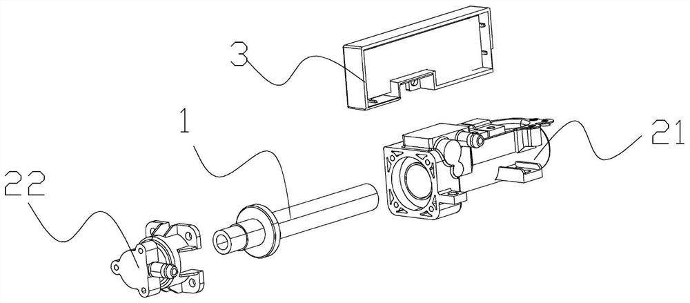
[0060] The resistance heating element 1 includes a resistance wire 11; the resistance wire 11 includes at least two groups of heating resistance wires 111 with different powers and a group of temperature control resistance wires 112; the temperature control resistance wire 112 is added, which can be more quickly and directly The change of the temperature of the resistance heating element 1 is monitored, the change of the fluid temperature and the actual flow rate are calculated, and then the heating power is adjusted before the fluid temperature changes.

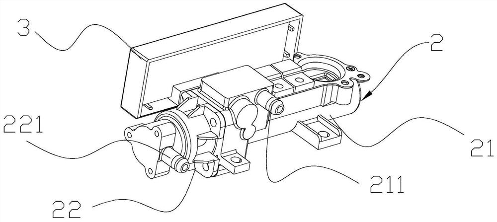
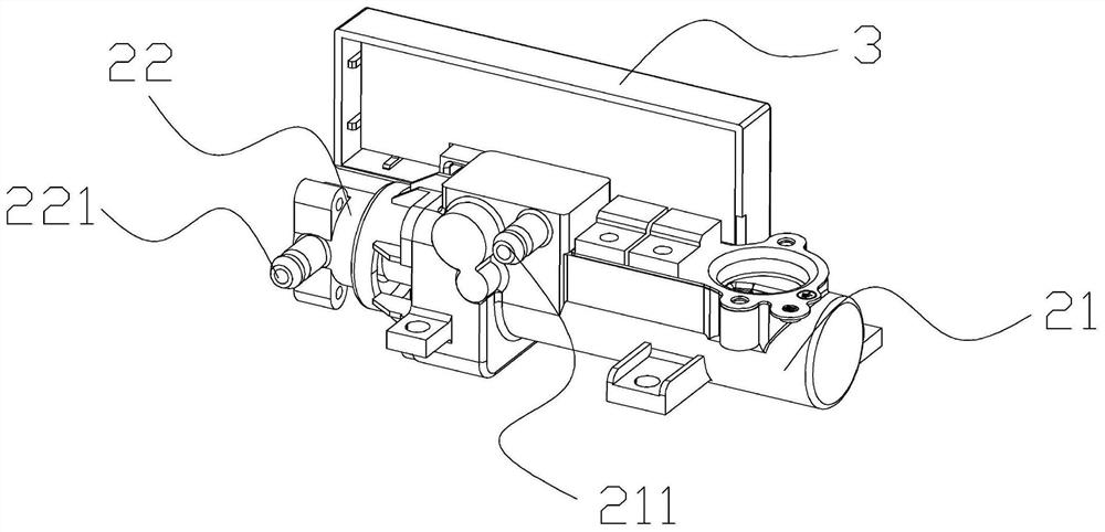
[0061] The fluid heating container 2 includes a main body 21 and a cover 22; the main body 21 and the cover 22 form an accommodating cavity inside, the cover 22 is provided with a fluid inlet 221, and the main body 21 is provided near the cover 22. There is a fluid outlet 211; the fluid enters the fluid heating container 2 fro...

Embodiment 2

[0089] like Figures 1 to 3 As shown, the present invention provides a fluid heater, comprising:

[0090] The resistance heating element 1 includes a resistance wire 11; the resistance wire 11 includes at least two groups of heating resistance wires 111 with different powers and a group of temperature control resistance wires 112; the temperature control resistance wire 112 is added, which can be more quickly and directly The change of the temperature of the resistance heating element 1 is monitored, the change of the fluid temperature and the actual flow rate are calculated, and then the heating power is adjusted before the fluid temperature changes.

[0091] The fluid heating container 2 includes a main body 21 and a cover 22; the main body 21 and the cover 22 form an accommodating cavity inside, the cover 22 is provided with a fluid inlet 221, and the main body 21 is provided near the cover 22. There is a fluid outlet 211; the fluid enters the fluid heating container 2 fro...


PUM


Abstract

The invention discloses a fluid heater and a control method thereof. The fluid heater comprises a resistance heating body which comprises a resistance wire, wherein a heating resistance wire and a temperature control resistance wire are arranged on the resistance wire, and the heating resistance wire comprises a thin resistance wire and a thick resistance wire; a fluid heating container comprisinga main body and a cover body, wherein a containing cavity is formed by the main body and the interior of the cover body, the cover body is provided with a fluid inlet, and the position, close to thecover body, of the main body is provided with a fluid outlet; and an electrical control system comprising a heating body temperature detection circuit. The resistance heating body is arranged in the containing cavity in the fluid heating container. The fluid heater and the control method thereof are convenient to use, the temperature of the heating body is sensed in real time by directly monitoring the change of the internal resistance of the resistance heating body, and the temperature of fluid in close contact with the heating body is calculated; and the structure of the fluid heater is simplified, and the stability of the outlet fluid temperature and the safety of the system are improved.

Description

technical field [0001] The invention relates to the technical field of heating, in particular to a fluid heater and a control method thereof. Background technique [0002] There are several technologies for fluid heating, one is heating method, the other is combustion method, but there are other ways to heat fluid, but in terms of environmental protection, although the first two methods can be used for fluid Heating treatment, but the combustion method is mainly to use the flame to burn, the flame will produce chemical substances such as methane, and has harmful substances such as carbon monoxide, so it is still harmful to the environment; while the other heating method is relatively environmentally friendly and does not No toxic substances that endanger the environment will be produced. When the fluid passes through the heating device, the harmful substances contained in the fluid can be catalyzed by high temperature, and then decomposed into harmless substances, so as to a...

Claims


Application Information

Patent Timeline
Patent Type & Authority Applications(China)
IPC IPC(8): F24H9/20F24H9/18F24H1/10G06F17/11
CPCF24H9/2028F24H9/1818F24H1/102G06F17/11
Inventor 平志雄翟红雨王锡敏
Owner 畅和智能家居(嘉兴)有限公司
Why Eureka
Try Eureka