Pipeline cleaning real-time monitoring system and method

A technology for real-time monitoring and pipeline cleaning, applied in cleaning methods and utensils, chemical instruments and methods, cleaning hollow objects, etc. Guarantee the effect of timeliness and simple operation

Pending Publication Date: 2020-11-10
SUZHOU WUZHONG WATER SUPPLY CO LTD
View PDF0 Cites 2 Cited by
  • Summary
  • Abstract
  • Description
  • Claims
  • Application Information

AI Technical Summary

Problems solved by technology

[0003] When using ice slurry to clean the water supply pipeline, the amount of water used can be obtained by calculation, and the flow rate can also be measured by a flow meter, but it is best to find an indicator that can reflect both the water amount and the flow rate during the cleaning operation, and is easy to operate; by detecting chloride ions in the water Concentration can determine the salt residue, but it is impossible to detect the concentration of chloride ions in real time at the job site, so it is necessary to find an indicator that can reflect changes in the concentration of chloride ions in real time at the job site; when cleaning the water supply pipeline, although the color of the discharged wastewater can be observed with the naked eye However, visual observation is too subjective, and the start and end times obtained will vary from person to person, and the accuracy is not high; measuring the amount of sediment flushed out of the pipe is the key to evaluating the effect of ice slurry cleaning water supply pipes indicators, but the washed out pipeline sediments are mixed with a large amount of ice water, and it is very difficult to directly collect the sediments by physical methods and weigh them.

Method used


Image

  • Pipeline cleaning real-time monitoring system and method

Examples


Embodiment Construction

[0034] The present invention is described in detail below in conjunction with accompanying drawing and specific embodiment:

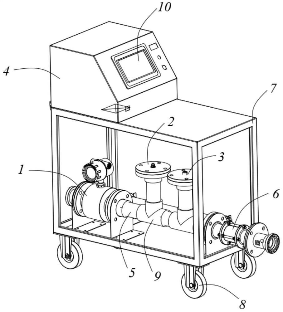
[0035] Such as figure 1 A real-time monitoring system for pipeline cleaning is shown, which is set at the outlet of the pipeline to be cleaned, including

[0036] The electromagnetic flowmeter 1 is used to detect the flow and flow velocity of the cleaning wastewater in the pipeline and convert it into an electrical signal;

[0037] The sludge concentration meter 2 is used to detect the sludge concentration and turbidity of the cleaning wastewater in the pipeline and convert it into an electrical signal;

[0038] The conductivity meter 3 is used to detect the conductivity and temperature of the cleaning wastewater in the pipeline and convert them into electrical signals;

[0039] And the information processing terminal 4, the information processing terminal 4 receives the electrical signals detected by the electromagnetic flowmeter 1, the sludge concen...


PUM


Abstract

The invention relates to a pipeline cleaning real-time monitoring system and method, the system comprises an electromagnetic flowmeter, a sludge concentration meter, a conductivity meter and an information processing terminal, and the information processing terminal receives electric signals detected by the electromagnetic flowmeter, the sludge concentration meter and the conductivity meter, processes the electric signals and displays the electric signals in real time. The method comprises the following steps: S1, detecting cleaning wastewater in a pipeline through a sludge concentration meterto obtain sludge concentration and turbidity, and calculating the weight of washed-out sediments according to the sludge concentration or turbidity; s2, detecting the conductivity and the water temperature of the cleaning wastewater in the pipeline through a conductivity meter; and S3, taking great increase of the conductivity or turbidity as a cleaning starting point, and taking reduction of theconductivity or turbidity as a normal level as a cleaning end point. After the system and the method are adopted, online display is achieved, the operation is simple, time and labor are saved, the stored data volume is large, the formula calculation requirement is met, and the timeliness of the data is ensured.

Description

technical field [0001] The invention relates to the technical field of pipeline cleaning, in particular to a pipeline cleaning real-time monitoring system and method for cleaning pipelines with ice slurry. Background technique [0002] When cleaning the water supply pipeline with ice slurry, how to save water as much as possible under the premise of ensuring the cleaning effect is very critical, and it is also necessary to control a certain flow rate so that the formed ice slurry passes through the pipeline at an optimal flow rate to obtain the best cleaning Effect: Accurately determine the start and end time of ice slurry cleaning, not only can calculate the time for ice slurry cleaning, but also start to collect flushing wastewater for subsequent treatment at the end of ice slurry cleaning, so as to better control the amount of cleaning wastewater collected; due to cleaning The ice slurry used in the pipeline is made of salt, so it is necessary to track the salt residue in...

Claims


Application Information

Patent Timeline
Patent Type & Authority Applications(China)
IPC IPC(8): G01F1/58G01P5/08G01N15/06G01N15/04G01N27/10B08B9/032B08B13/00
CPCB08B9/0321B08B13/00G01F1/58G01N15/04G01N15/06G01N27/10G01P5/08
Inventor 彭秀华程志强赵吉陈志伟施凯
Owner SUZHOU WUZHONG WATER SUPPLY CO LTD
Why Eureka
Try Eureka