Gas-liquid two-phase jet flow oil pipe outer surface cleaning experiment device and method

An experimental device and external surface technology, applied in the direction of measuring devices, flow characteristics, instruments, etc., can solve the problems of high nozzle structure requirements, affecting cleaning effect, consuming jet energy, etc., to achieve good cleaning effect, reasonable experimental design, and real-time measured effect

Pending Publication Date: 2020-11-10
SHENGLI COLLEGE CHINA UNIV OF PETROLEUM
View PDF0 Cites 2 Cited by
  • Summary
  • Abstract
  • Description
  • Claims
  • Application Information

AI Technical Summary

Problems solved by technology

The study found that the bubbles generated by the cavitation jet will generate a lot of energy at the moment of collapse, and the cleaning effect is better, but the nozzle structure of the cavitation jet has higher requirements, and spontaneous cavitation will consume a certain amount of jet energy, which will affect the cleaning effect

Method used


Image

  • Gas-liquid two-phase jet flow oil pipe outer surface cleaning experiment device and method
  • Gas-liquid two-phase jet flow oil pipe outer surface cleaning experiment device and method
  • Gas-liquid two-phase jet flow oil pipe outer surface cleaning experiment device and method

Examples


Embodiment 1

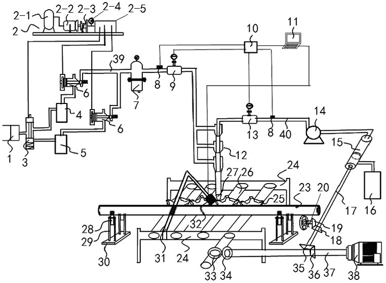
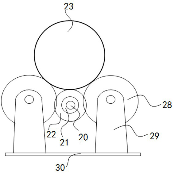
[0038] Embodiment 1, an experimental device for cleaning the outer surface of a gas-liquid two-phase jet oil pipe mentioned in the present invention, including a screw air compressor 1, a hydraulic workstation 2, a hydraulically controlled two-position three-way valve 3, an air storage tank 4, and a spare storage tank. Gas tank 5, hydraulic control check valve 6, precision gas filter 7, pressure sensor 8, vortex flowmeter 9, data acquisition system 10, computer 11, three-stage gas-liquid mixer 12, turbine flowmeter 13, high-pressure screw Pump 14, automatic centrifugal filter 15, water storage tank 16, centrifugal shaft 17, first bevel gear 18, second bevel gear 19, rotating transmission shaft 20, transmission sleeve 21, elastic friction layer 22, oil pipe to be cleaned 23, Transmission bracket 24, linkage roller 25, transmission roller 26, nozzle 27, roller 28, oil pipe support frame 29, support plate 30, fixed bracket 31, high-speed camera 32, third bevel gear 33, fourth beve...

Embodiment 2

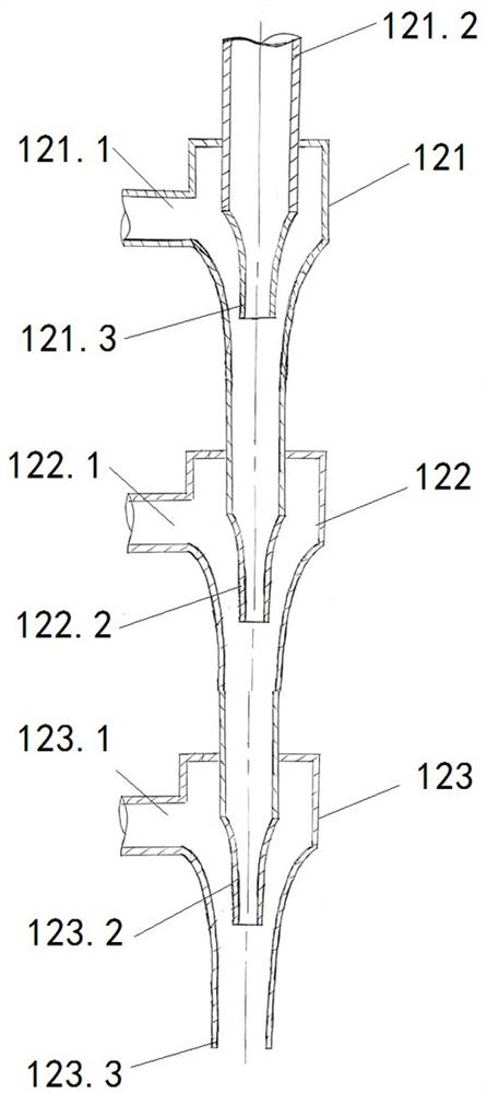
[0063] Embodiment 2, the gas-liquid two-phase jet oil pipe outer surface cleaning experimental device mentioned in the present invention, differs from Embodiment 1 in that: the three-stage gas-liquid mixer 12 mentioned in the present invention includes a primary gas-liquid mixing chamber 121 , the secondary gas-liquid mixing chamber 122, the tertiary gas-liquid mixing chamber 123, the top center of the primary gas-liquid mixing chamber 121 is provided with a first liquid inlet 121.2, the outer side is provided with a first gas inlet 121.1, and the first liquid inlet 121.2 is connected to The lower end of the first central liquid pipe is the first liquid outlet 121.3, and the two-phase flow formed by the preliminary mixing of liquid and gas from the first liquid outlet 121.3 enters the secondary gas-liquid mixing chamber 122, and is sprayed out through the second liquid outlet 122.2 The second gas inlet 122.1 is provided on the outside of the secondary gas-liquid mixing chamber ...

Embodiment 3

[0065] Embodiment 3, the experimental device for cleaning the outer surface of the gas-liquid two-phase jet oil pipe mentioned in the present invention, differs from Embodiment 2 in that: the cavity of the gas-liquid mixing chamber of each stage is composed of a gas channel a, a contraction section b, Composed of cylindrical section c and expansion section d; a plurality of gas channels are evenly and staggeredly distributed on the circumference of the gas-liquid mixing chamber, and are located in different horizontal directions, so that the gas-liquid can be mixed more fully.


PUM


Abstract

The invention relates to a gas-liquid two-phase jet flow oil pipe outer surface cleaning experiment device and method. According to the technical scheme, the device comprises a screw air compressor, ahydraulic workstation, a hydraulic control two-position three-way valve, an air storage tank, a hydraulic control one-way valve, a precision air filter, a pressure sensor, a vortex shedding flowmeter, a data acquisition system, a computer, a three-stage air-liquid mixer, a turbine flowmeter, a high-pressure screw pump, an automatic centrifugal filter, a water storage tank, a nozzle and the like.The device has the beneficial effects that high-pressure water and high-pressure gas can be mixed to form stable gas-liquid two-phase jet flow, opening and closing of a valve can be hydraulically andremotely controlled, automatic conveying and automatic rotating of an oil pipe can be achieved, parameters such as pressure, flow and the surface cleaning effect can be measured, stored and displayedin real time, and hydraulic control and electric control are combined; the device is simple in structure, high in safety coefficient, reasonable in experimental design and good in cleaning effect, canobtain related data information of oil pipe cleaning experiments and provides basic theoretical basis for oil pipe cleaning technologies.

Description

technical field [0001] The invention relates to a device and a method for cleaning the outer surface of an oil pipe, in particular to an experimental device and method for cleaning the outer surface of a gas-liquid two-phase jet oil pipe. Background technique [0002] The oil pipe is one of the essential equipment for the exploitation of oil and gas resources. It plays a very important role in the oil development process. It is used in a large amount and the cost is high. After a period of oil field development, the oil pipe is easy to form dirt in the high temperature and high pressure environment, such as oil stains , scale, coke-like substances, sediments, etc., reduce the flowable area of ​​the tubing, increase the flow loss, reduce the efficiency of oil and gas extraction, and even stop production due to complete blockage, seriously affecting the overall benefits of oil and gas extraction. [0003] With the increasing difficulty in the development of high water-cut oilf...

Claims


Application Information

Patent Timeline
IPC IPC(8): G01N11/00
CPCG01N11/00
Inventor 时凤霞赵健石洋李春杰王保强徐依吉刘新亮
Owner SHENGLI COLLEGE CHINA UNIV OF PETROLEUM
Why Eureka
Try Eureka